Step 6: Build a Quasi-Dynamic Scenario
In the previous steps of this beginner tutorial, you created a simple thermal network and carried out a steady state simulation. In doing so, you assumed an equilibrium condition in your system and took a snapshot of its state. Now, you will learn how to perform a full dynamic simulation and explore how your system’s state evolves in time.
|
If you closed SAInt at the previous step and saved your work, you can restart from where you left off by following these steps:
Alternatively, you can get a copy of the tutorial’s data from the SAInt User Forum. Check the category "Model Ready Datasets" for the latest version of the tutorial data downloads. |
1. Scenario creation
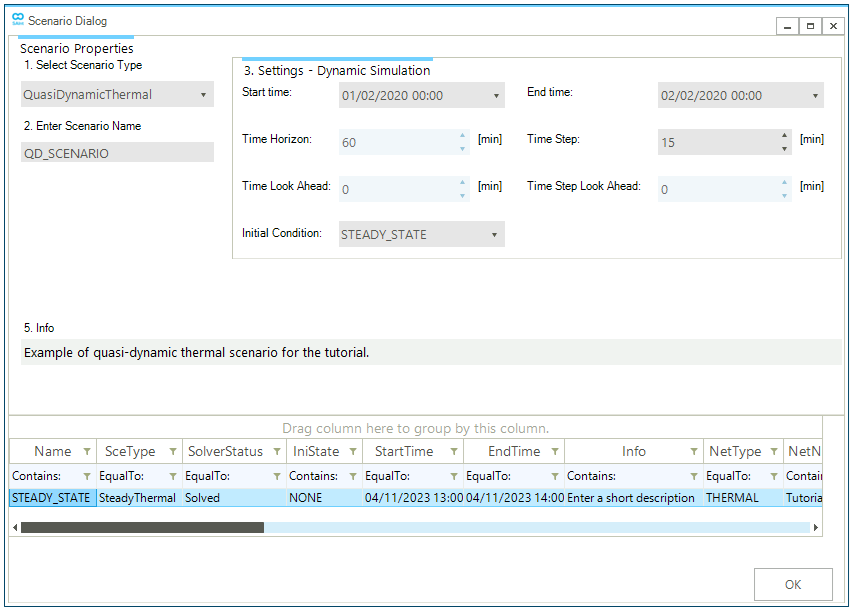
Create a new quasi-dynamic scenario by going to the scenario tab and selecting . This will open the scenario dialog window, where you will define the parameters and settings of the scenario. As in the case of the steady state scenario of step 3, you first need to define the scenario type. In the top left corner under 1. Select Scenario Type click on the drop-down menu and select QuasiDynamicThermal. Under the 2. Enter Scenario Name enter QD_SCENARIO as shown in Figure 1.
Section 3. Settings - Dynamic Simulation is now active and allows the definition of the scenario’s start and end time, and the time step of the simulation, and from which scenario to copy the initial conditions. The simulation encompasses one full day from 00:00 a.m. February 01, 2020, to 00:00 a.m. February 02, 2020. Next, manually insert the time values or use the drop-down option. The time step is set to 900 seconds or 15 minutes. And you will use the solution of the steady state scenario STEADY_STATE as the initial condition (see Figure 1).
Finally, you can enter a short description of your new scenario in 5. Comment. The scenario name defines the file name. In this case, the file will be named QD_SCENARIO.tsce. Once completed, click OK at the bottom of the window. A prompt will show up that indicates the scenario was created successfully. Close the window or press OK to continue.
|
Remember that a quasi-dynamic scenario does not require the user to specify its initial conditions. But we advise to use an initialization state to better handle charts and tables for the initial time step. |
2. Adding events without profiles
As in the steady state case of step 4, you can add new events to the quasi-dynamic scenario using either the model explorer or the map window and the node bar. Start by selecting the object HDEM.HDEMAND5 in the model explorer, right-click to access from the context menu. As before, a new window opens where you can define the event’s properties. Set Value to 1 MW. Leave all other properties to their default values. Repeat the operation and use of 1 °C. Leave the rest to the default values. You will define the profile for these events in the next step.
Use Table 1 and Table 2 to complete the initial version of this quasi-dynamic scenario. We are using a similar setup to the steady state case, but we have introduced time.
You can open the events table and quickly review the events you have added to be correct.
If you run the simulation now, you will generate a sequence of equal steady states because there is no event where a profile or any type of time dependency is specified.
| Demand Name | Event | Value | Unit of measure |
|---|---|---|---|
DEMAND2 |
|
30 |
°C |
DEMAND3 |
|
35 |
°C |
DEMAND4 |
|
30 |
°C |
DEMAND5 |
|
1 |
°C |
DEMAND9 |
|
30 |
°C |
DEMAND10 |
|
35 |
°C |
DEMAND2 |
|
0.4 |
MW |
DEMAND3 |
|
0.9 |
MW |
DEMAND4 |
|
0.4 |
MW |
DEMAND5 |
|
1.0 |
MW |
DEMAND9 |
|
0.2 |
MW |
DEMAND10 |
|
0.7 |
MW |
| Demand Name | Event | Value | Unit of measure |
|---|---|---|---|
SUPPLY6 |
|
70 |
°C |
SUPPLY7 |
|
90 |
°C |
SUPPLY6 |
|
2.4 |
MW |
SUPPLY7 |
|
2.0 |
MW |
SUPPLY6 |
|
1 |
- |
|
Because the events are the same as the ones in the steady state case (with the exception of DEMAND5), it is also possible to include what we have already in the scenario STATEDY_STATE. Use . ANd after change the values for the events linked to DEMAND5. |