Build a SteadyACPF Scenario
In the previous steps of the tutorial we created an electric network represented by a flag-shaped power system. Now, we will create a SteadyACPF scenario. The objective is to learn how to create a scenario in SAInt and how different parameters affect the behavior of the scenario.
|
If you paused the tutorial at the previous step. Before starting this tutorial, follow the steps below to open the previously created network file.
|
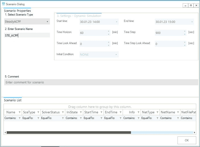
1. Scenario general settings
Create a new scenario by going to the scenario tab and selecting the . This will open the scenario dialog window. Here we will define the parameters and settings of the scenario. The first step is to define the scenario type in the top left corner under 1. Select Scenario Type. Click on the drop-down menu and select SteadyACPF. Under 2. Enter Scenario Name, type STE_ACPF (Figure 1). The scenario name will also be used to name the scenario file. In this case, the file will be named STE_ACPF.esce. Once completed, click on OK at the bottom of the window. A prompt will show up that indicates the scenario was created successfully. Close the window or press OK to continue.
2. Design Steady ACPF Events
In SAInt, events are used to change default values, settings, and controls at specified times during the scenario time window. This step will focus on designing scenario events to define the active/reactive power set points for the demand and generator objects. The objective is to understand how to define scenario events to influence the behavior of your model.
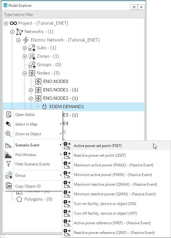
2.1. Create demand event via the model explorer
We will start by defining the electrical demand on the system. Using the model explorer, we will add one PSET event for DEMAND1, which sets the active power of an object at a given time step. Find the DEMAND1 object by going to the , then right-click on the demand object and select (Figure 2). This will automatically create the event and prompt the property editor window for the event.
2.2. Create generator events using the node explorer
Scenario events can also be created using the node explorer. The node explorer displays all objects (branches and externals) connected to a selected node. Open the node explorer by clicking on the Node in the ribbon bar tab "View". Undock the node explorer window and place it so that you can see the map view and the node explorer windows at the same time. Select NODE1 in the map window and right click. Select the option "Select in Node Explorer" to view the generic generator NG_GEN2 in the node explorer (Figure 3). Right-click on NG_GEN2 and create a PSET event to model the scheduled power supply. Close the event property editor window, as the event properties will be defined later using the event table (EEVT). Repeat these steps using the node diagram of NODE3 to create the PSET event for the generic generator NG_GEN1.
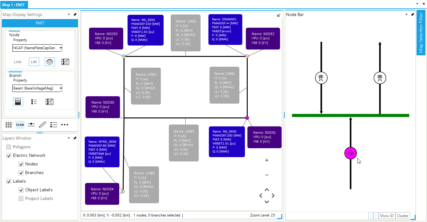
The final step for completing the events for the SteadyACPF scenario is to add the events for the wind generator WIND_GEN3. Please use either the node bar or the model explorer to define the PSET and reactive power set point QSET events for WIND_GEN3 connected to NODE4.
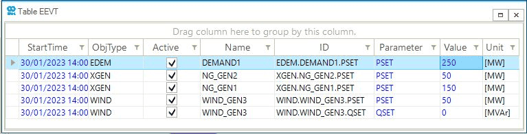
2.2.1. Edit event properties in the event table
The event table can be used to review, filter, and edit scenario events. Open the event table by going to the scenario tab and clicking on EEVT. Once opened, you should view a table with five scenario events. Now, we can directly edit the event properties in the table. For the PSET events of NG_GEN1 and NG_GEN2, add the values 150 and 50 in the Value column, respectively. For the wind generator WIND_GEN3, add the value 50 for the PSET event and 0 for the QSET event. The 0 value for the QSET event is applied to ensure the unit power factor (no voltage control). After defining the values for all the scenario events, the event table should look similar to Figure 4.