Step 6: Build a Dynamic Scenario
In the previous steps of this beginner tutorial, you created a simple gas network, and carried out a steady state simulation. In doing so, you assumed an equilibrium condition in your system and took a snapshot of its state. Now, you will learn how to perform a full dynamic simulation and explore how your system’s state evolves in time.
|
If you closed SAInt at the previous step and saved your work, you can restart from where you left off by following these steps:
|
1. Scenario creation
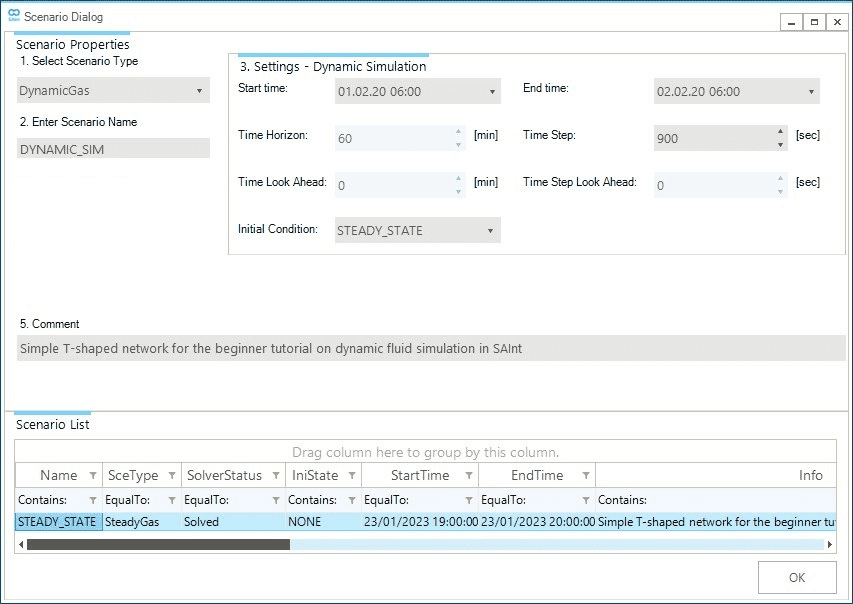
Create a new dynamic scenario by going to the scenario tab and selecting . This will open the scenario dialog window, where you will define the parameters and settings of the dynamic scenario. As in the case of the steady state scenario of step 3, you first need to define the scenario type. In the top left corner under 1. Select Scenario Type click on the drop-down menu and select DynamicGas. Under the 2. Enter Scenario Name enter DYNAMIC_SIM as shown in Figure 1.
Section 3. Settings - Dynamic Simulation is now active and allows the definition of the scenario’s start and end time and the time step of the simulation, and from which scenario to copy the initial conditions. The simulation encompasses one full day from 06:00 a.m. February 01, 2020, to 06:00 a.m. February 02, 2020. Next, manually insert the time values or use the drop-down option. The time step is set to 900 seconds or 15 minutes. And you will use the solution of the steady state scenario as the initial condition (see Figure 1).
Finally, you can enter a short description of your new scenario in 5. Comment. The scenario name defines the file name. In this case, the file will be named DYNAMIC_SIM.gsce. Once completed, click OK at the bottom of the window. A prompt will show up that indicates the scenario was created successfully. Close the window or press OK to continue.
|
Remember that a dynamic scenario requires the user to specify its initial conditions. Those could be either the solution from a steady state or a dynamic scenario. |
2. Adding events without profiles
As in the steady state case in step 4, you can add new events to the dynamic scenario using either the model explorer or the map window and the node bar. Start by selecting the object GDEM.DEMAND1 in the model explorer, right-click to access from the context menu. As before, a new window opens where you can define the event’s properties. Set Value to 100 ksm3/h. Leave all other properties to their default values. You will define the profile for this event in the next step.
Add the same type of event to object GDEM.DEMAND2 and object GDEM.DEMAND3 with values 80 and 1 ksm3/h, respectively. Yes, this is not a mistake! You will use profiles in two ways to modulate the demand of object GDEM.DEMAND3 versus object GDEM.DEMAND1 and GDEM.DEMAND2.
You are not specifying any event for GSUP.SUPPLY1 or the control valve. Their status is defined and copied from the steady state scenario initializing your dynamic simulation.
You can open the events table and quickly review the events you have added to be correct.