Add External Objects
The final step in creating the AC power flow model is to add external objects to the nodes of the power system. External objects in SAInt are used to inject or extract energy from the node. This tutorial will focus on creating the demand and generator externals for the flag-shaped power system. The objective is to learn different methods to create external objects and define their properties. A future tutorial will explain in detail how these properties affect the behavior of the different externals.
|
Each external object must be assigned to a node object within the network, and there is no limitation on the number of externals assigned to a node. |
1. Add demand via the map window
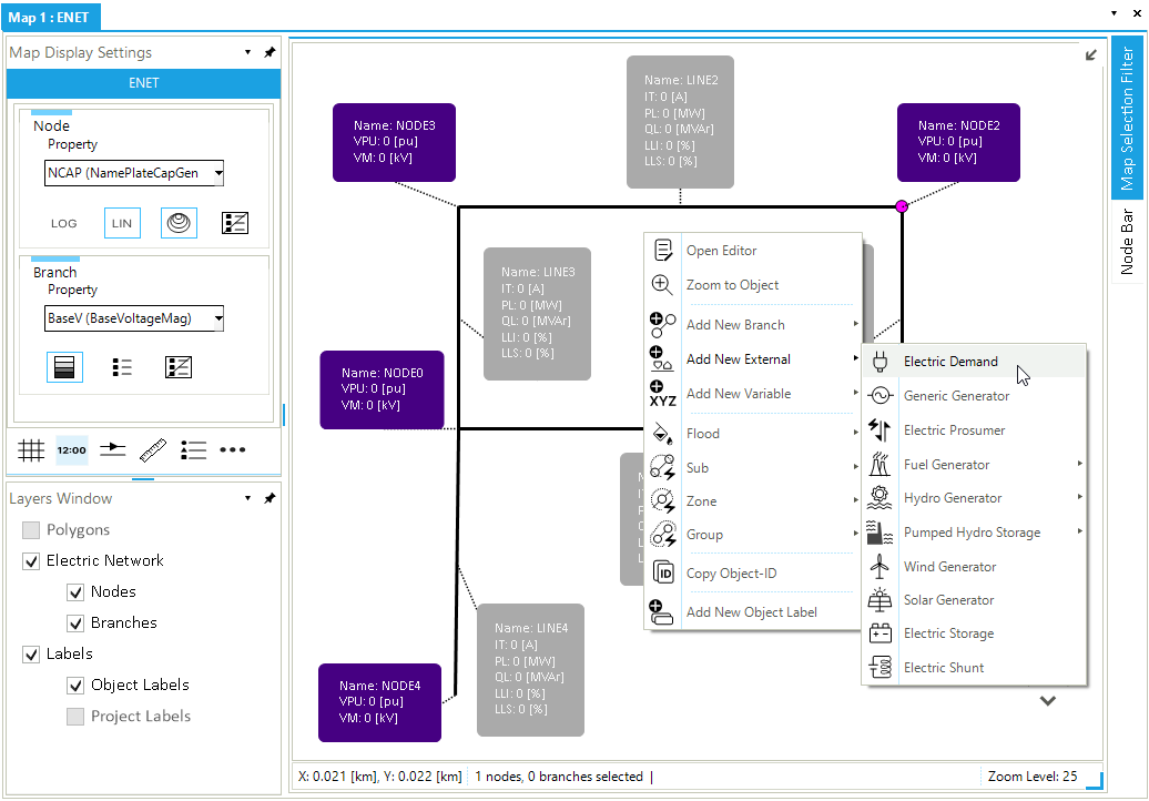
Externals can be added to a network in multiple ways. We will first use the map window. Right-click on NODE2 and use the option from the context menu (Figure 1). Once selected, the property editor of the electrical demand object will appear. Use the property editor to change the Name to DEMAND1, power factor (PWF) to 0.85. Moreover, select ind from the drop-down menu of the power factor type (PWFType) property.
|
The ind property value represents an inductive load, while res and cap represents a capacitive and resistive load, respectively. |
2. Add generic generators via the model explorer
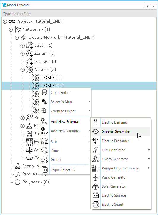
The model explorer on the left side of SAInt GUI can also be used to add external objects. Right-click on NODE1 in the model explorer and select . Once selected, the property editor of the generic generator (XGEN) object will appear. Before defining the generator properties, we will add a second generic generator to NODE3 by following the same procedure.
2.1. Define generic generator properties
We can define the properties of generic generators via the property editor or an object table (accessible from on the ribbon bar). Use Table 1 shown below to define the properties of the two generic generators. These properties model generators' operational limits and voltage magnitude set points.
| Name | Node name | Default maximum active power | Default minimum active power | Default maximum reactive power | Default minimum reactive power | Default active power compensation factor | Deafult voltage magnitude set point |
|---|---|---|---|---|---|---|---|
|
|
|
|
|
|
|
|
NG_GEN1 |
NODE3 |
250 |
90 |
200 |
-200 |
80 |
1.03 |
NG_GEN2 |
NODE1 |
200 |
30 |
160 |
-160 |
20 |
1.01 |
|
3. Add wind generator object
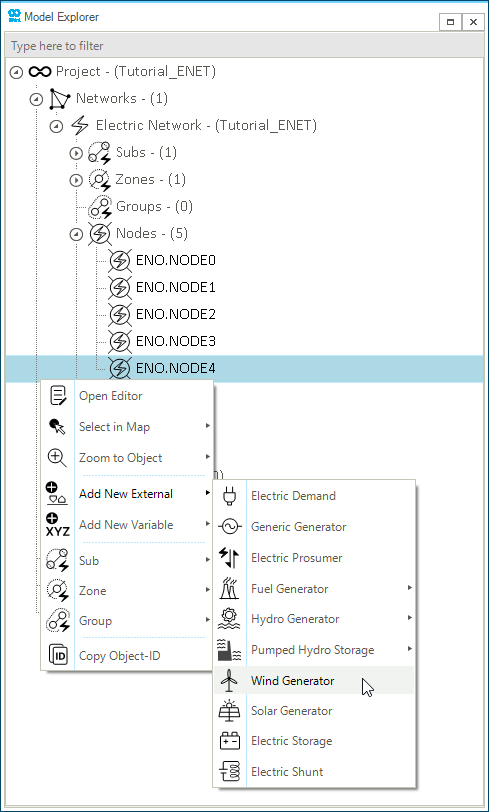
Finally, add a wind generator to NODE4 using the model explorer. Select from the context menu of NODE4 (Figure 3). Use the property editor to change the (Name) to WIND_GEN3, and default maximum active power (PMAXDEF) to 80 [MW]. Open the GEN object table from on the ribbon bar to ensure that the properties of the three generators have been defined correctly.
4. Add labels for the externals
Using the map window, let’s add labels to the three generators and one demand object. Right-click on NODE1 and select . Once the label is displayed on the map window, edit the label properties using the property editor of the label. Right-click on the label and select Open Editor. From here, we will edit the label information to display the following properties:
-
Object name (
Name) -
Default maximum active power (
PMAXDEF) -
Active power set point (
PSET) -
Voltage magnitude set point (
VMSET) -
Active power (
P) -
Reactive power (
Q)
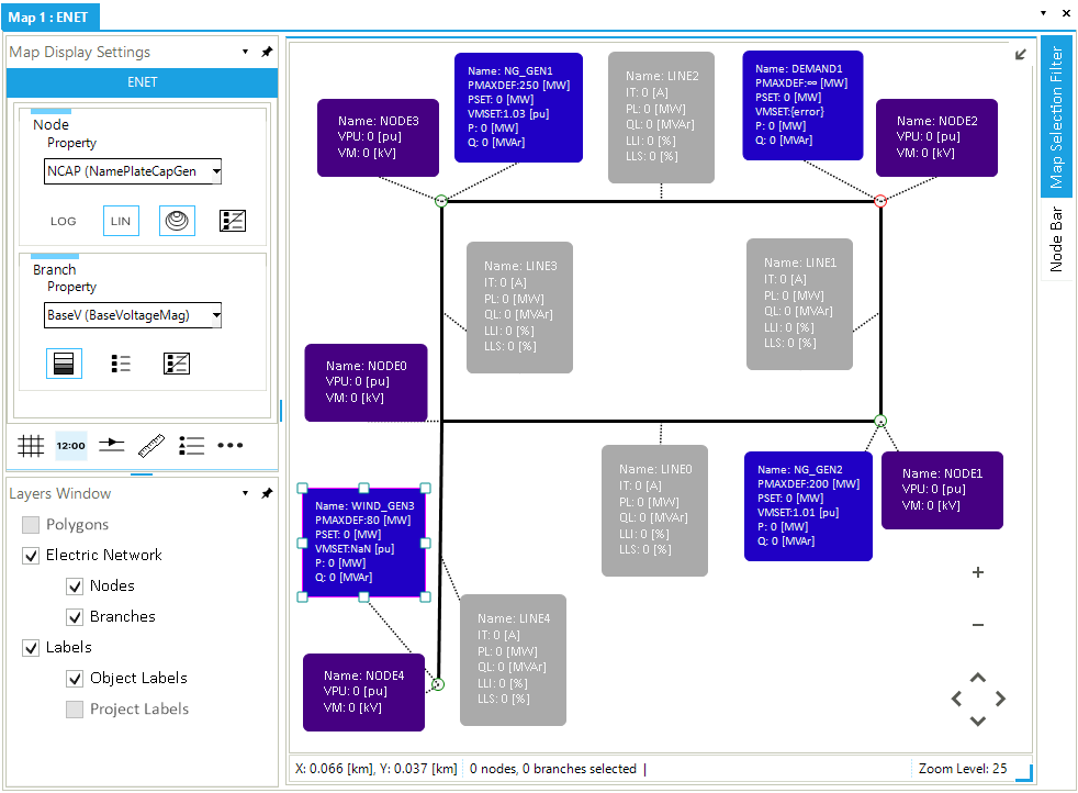
In the property editor window, change the LabelInfo property to Name: {@.Name}, PMAXDEF: {@.PMAXDEF}, PSET: {@.PSET}, VMSET: {@.VMSET}, P: {@.P}, Q: {@.Q}. The label’s look can be edited by changing the different properties under the background, font, frame, and visibility categories. Optionally, you can use Table 2 to edit the look of external labels (Figure 4). Next, follow the same procedure to add labels for NG_GEN1, DEMAND1, and WIND_GEN3. Refer to Figure 4 for the LabelInfo property values for other generators and demand objects.
Click here for more details about custom external labels.
| Background | |
|---|---|
FillColor |
32,0,197 |
| Font | |
|---|---|
LabelFont |
Calibri, 8pt |
LabelFontColor |
245,245,245 |
| Frame | |
|---|---|
LabelFrameVisible |
TRUE |
RoundedLabelFrame |
TRUE |
StrokeWidth |
1 |
FrameColor |
32,0,197 |
| Visibility | |
|---|---|
LabelVisible |
TRUE |
LabelStartZoomLevel |
25 |
LabelUntilZoomLevel |
27 |
LabelOpacity |
100 |