Step 1: Create an Electric Network Model and CEM Scenario
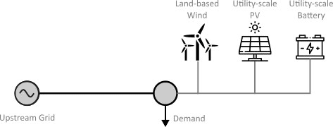
We create a simple electric network, which will represent a power system where a grid-connected microgrid can import power from the upstream grid. You will later use this network to create a CEM model in SAInt. The power system consists of two electric nodes, one line, one generic generator representing the upstream grid, one wind generator, one PV generator, one electric storage, and one demand object. A schematic of the network is shown below:
1. Define Network Topology and Externals
Start by opening the included network MICROGRID.enet in SAInt. Verify that the nodes, branches, and externals are laid out as shown in the screenshot below:
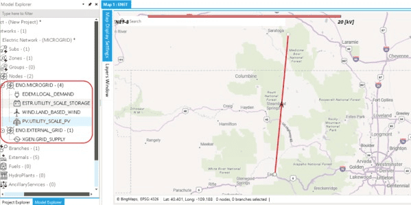
|
In CEM scenarios, object properties are specified using CSV files. As long as your objects are named correctly in the GUI, you are good to go! |
|
You can also build this network in SAInt yourself. For a more detailed tutorial on how to create nodes, branches and externals, please refer to the beginner’s tutorial on Electricity Networks ("Create an Electric Network Model"). |
2. Create a CEM scenario
The next step is to create a CEM scenario. In the present design, all CEM scenarios contain the same information. Therefore, just ensure that the CEM.esce file from the tutorial folder is present in the same location as the network file.
|
When you create a new CEM model, you can simply copy and paste the scenario file CEM.esce without any modifications to your model folder. |