Step 1: Create a Thermal Network Model
This step is the first in your journey to becoming an expert using the SAInt GUI for thermal network modeling. This tutorial series starts with creating a simple model to simulate a steady state thermal network. A network object contains and defines all the default and static properties of a system. The thermal model will consist of ten nodes, nine lines, two heat supply and six heat demand objects.
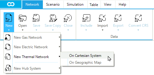
1. Create a new network
Start by opening SAInt and creating a new default thermal network. Go to the network tab and select as in Figure 1. This action will automatically open a window asking for a folder where to save the network. The newly created network file will share the same name as the folder. See next step for naming the folder.
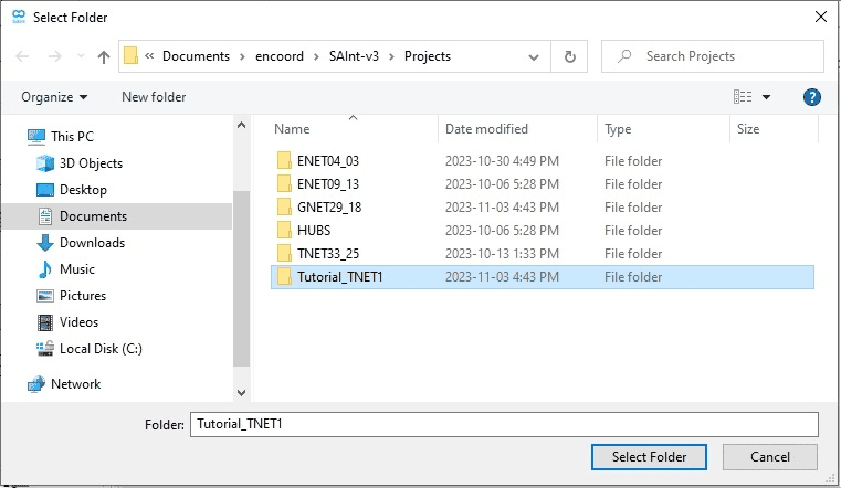
2. Select network file location
By default, SAInt will open the Projects folder in SAInt’s user folder (C:\...\Documents\encoord\SAInt-v3\Project). Notice in the same folder the availability of sample networks developed for you by encoord. Create a new folder by right-clicking in the window and selecting or using the button "New Folder". Name the new folder Tutorial_TNET1. Now with the Tutorial_TNET1 folder selected, click Select Folder in the bottom right-hand corner of the window, as shown in Figure 2. The Tutorial_TNET1 folder will be your project folder to host all the files related to our SAInt model.
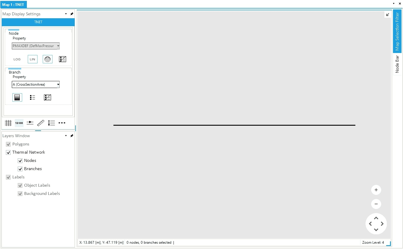
3. New default thermal network
A text box will show that the Tutorial_TNET1 network was created and successfully loaded into SAInt. Click OK and check the result in the map window. The new network already has two nodes and one branch, as shown in Figure 3. In SAInt, a network always has at least one branch and two nodes.
|
You can change all basic properties of your network by modifying the items in blue in the Property editor. Select the network in the Model Explorer and open the Property Editor. If it is not there, just right-click and select it from the context menu. |
|
The network and the active scenario available in the current SAInt GUI session are always shown on the left side of the status bar at the bottom of the screen. |
|
When you start a new project, remember to check the units of measurement used. Right-click on |
