Step 3: Add External Objects
The final step in creating the energy market model is to add external objects to the nodes of the power system. External objects in SAInt inject or extract energy from the node, thus, the network. This tutorial will focus on creating the demand and generator objects for the triangular power system. The objective is to learn different methods to create external objects and define their properties. Future tutorials will explain in detail how these properties affect the behavior of the other externals.
|
Externals are assigned to a single node object within the network, and there are no limitations on the number of externals that can be assigned to a node. |
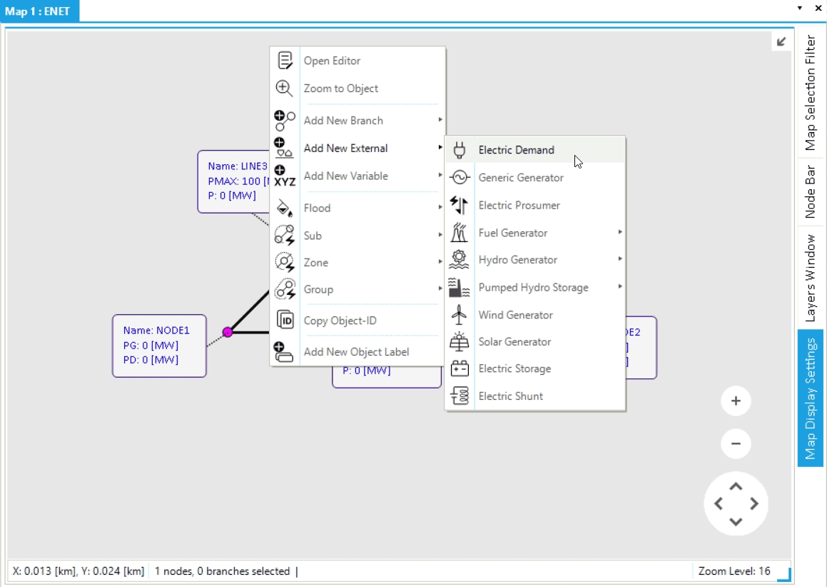
1. Add demands via the map window
Externals can be added to a network by multiple methods. You will first use the map window. Right-click on NODE1 and use the option from the context menu, as shown in Figure 1. Once selected, the property editor of the electric demand object will appear. Change the name of the new external to DEMAND1 and leave the remaining properties with the default values. Use the same process to add a demand object named DEMAND2 to NODE2.
2. Add fuel generators via the model explorer
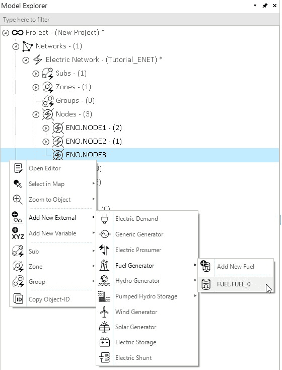
The model explorer on the left side of the screen can also be used to add external objects. Right-click on NODE1 in the model explorer and select . Each fuel generators must have an assigned fuel object. Fuel objects can be assigned to more than one fuel generator. Once it is selected, notice that two property editor windows are prompted, one for each object.
Before defining the new object’s properties, you will add a second generator to NODE3. Right-click on the node and select the option; however, now there are two options, one to assign the generator to a new fuel or the previously created fuel (FUEL_0). In this case, select FUEL.FUEL_0 to assign the generator to the already existing fuel, as shown in Figure 2.
3. Define fuel and fuel generator properties
Open the fuel property editor window by selecting the FUEL_0 in the model explorer.
You will start by naming the fuel as NATGAS.
Now, under the fuel category, define the FuelUnit and FuelPrice properties as [MMBTU] and 7 [$/MMBTU] [1], respectively.
Finally, under the emission category, define the CO2EmissionPerFuelUnit property as 52910 [g/MMBTU] [2].
|
Properties related to the fuel’s |
You can now define the properties of the fuel generators via the property editor or object table. Use Table 1 shown below to determine the properties of the two fuel generators. These properties are used to model each generator’s operational costs and constraints.
Details
| Name | Default maximum active power | Default minimum active power | Linear fuel consumption coefficient | Constant fuel consumption coefficient |
|---|---|---|---|---|
|
|
|
|
|
NG_GEN1 |
100 |
10 |
7.5 |
3 |
NG_GEN2 |
100 |
10 |
7.5 |
5 |
| Name | Default startup price | Default variable operational and maintenance cost | Default maximum upward ramp rate | Default maximum downward ramp rate |
|---|---|---|---|---|
|
|
|
|
|
NG_GEN1 |
1000 |
1 |
0.5 |
0.5 |
NG_GEN2 |
2000 |
2 |
1 |
1 |
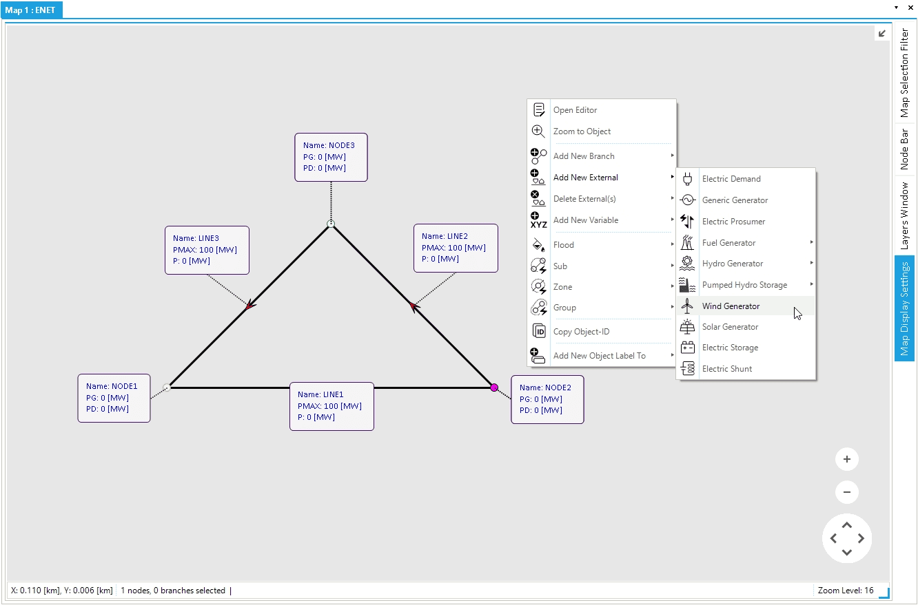
4. Add wind generator object
Finally, as shown in Figure 3, add a wind generator to NODE2 by right-clicking on the node and selecting .
For the wind generator properties, define the Name and PMAXDEF as WIND_GEN3 and 200 [MW], respectively.
Open the generator object GEN table to ensure the properties of the three generators have been defined correctly.
Notice that the properties not shared among the different generators will not be visible in the generator table.
These properties include fuel consumption, startup cost, and fuel name.
|
Wind and solar photovoltaic generators have a unique parent object type not valid for other generators called variable renewable generators (VRG). |