Create Hub Facilities in a Hub System
The hub facilities in SAInt are created by coupling network objects from the two distinct energy networks. This guide shows how to couple electric and gas network objects using model explorer and map window to create an electric-driven gas compressor (EDGCS). Steps are shown using the default networks under the project hub HUBS, after removing all existing labels. The information in this guide can be followed to create any other hub facility in SAInt, depending upon the network components.
|
An EDGC models the electric power consumption required to operate the electrical driver of a gas compressor. Therefore, a EDGCS hub facility couples an electric demand (EDEM) with a gas compressor (GCS). |
1. Create a hub using the model explorer
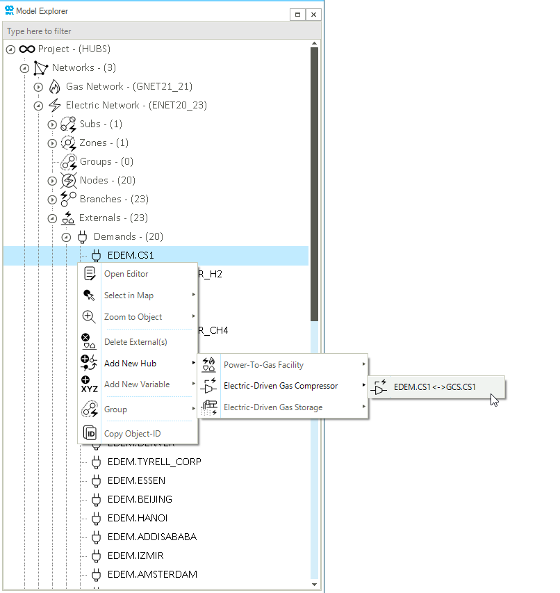
From the model explorer, select either the GCS or EDEM object. In this example an EDEM object is selected from . From the context menu, select The Add New Hub option. The menu lists all the possible hub facilities that can be created using the EDEM object. In this case, select the Electric Driven Gas Compressor option and the GCS to be coupled with the EDEM object to create the new EDGCS hub facility, as shown in Figure 1.
| Network objects can only be coupled to a single hub facility. Therefore, once a hub is created, the Add New Hub option disappears from the context menu of the coupled objects. |
2. Create a hub using the map window
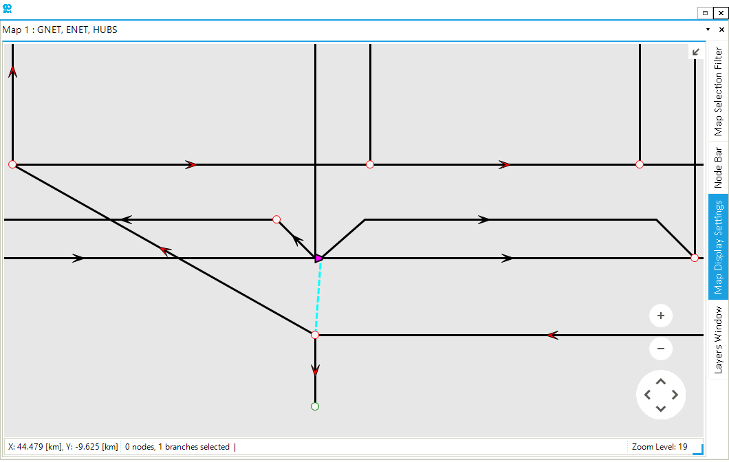
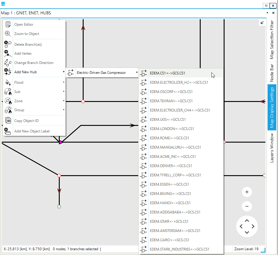
Additionally, the hub can also be created via the map window using either the GCS or EDEM object. In this example, the GCS is selected. Right-click to open the context menu and select The Add New Hub option. The menu lists all the possible hub facilities that can be created using the GCS object. Afterwards, select the EDEM object to be coupled with the GCS object to create the new EDGCS hub facility, as shown in Figure 2.
After following the steps above, the hub facilities are displayed in the model explorer under . The map window also shows the coupling point between the two network objects with a green dashed line, as shown in Figure 3.