Define Properties of a Gas Storage
This guide provides step-by-step instructions on how to edit the main properties of a gas storage. SAInt models a gas storage in general terms, allowing for a flexible representation of different type of storage objects along with a basic, but exhaustive, set of properties. In this way, SAInt can describe traditional natural gas "underground gas storages" (UGS), like depleted fields, salt caverns or aquifers, as well as above-ground tanks for other types of gasses.
For more information on how to create or or delete a gas storage refer to Create and Delete a Gas Storage.
|
Gas storage properties can only be changed in a network, and not in a scenario or a simulation. |
1. Editing properties for a gas storage object
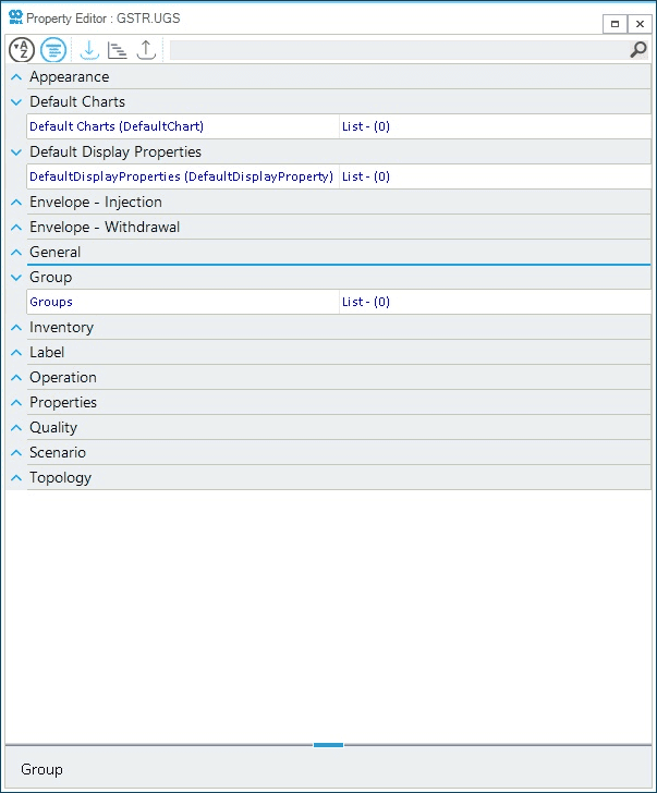
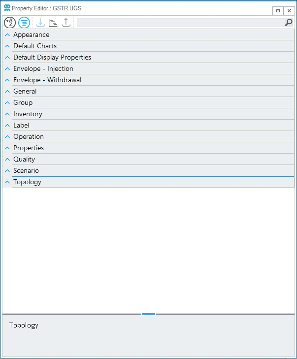
The easiest way to access and edit all relevant properties of a gas storage object is by using the property editor on the object. Alternatively, it is possible to edit properties from the the table of gas storages from . Figure 1 provides an overview of the sections grouping gas storage properties.
2. General properties and appearance
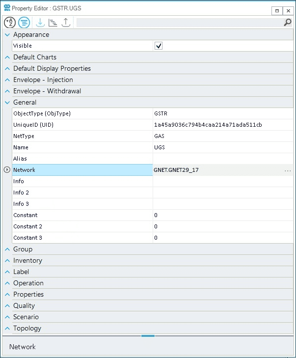
General editable properties for a gas storage are the name of the object, the alias, and the additional information fields (Figure 2). Furthermore, the user can check the list of labels associated to the object and turn on/off their visibility by ticking the option in the "Appearance" section.
3. Envelope injection and withdrawal
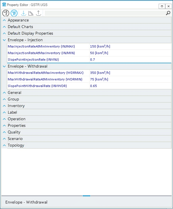
The operational envelope of the gas storage is defined by setting the constraints presented in the section "Envelop - Injection" and "Envelop - Withdrawal" (Figure 3). The user can choose to specify:
- MaxInjectionRateAtMinInventory
-
Use the
INJMAXproperty to define the maximum storage injection rate at the minimum working inventory. - MaxInjectionRateAtMaxInventory
-
Use the
INJMINproperty to define the maximum storage injection rate at the maximum working inventory. - SlopePointInjectionRate
-
Use the
INVINJproperty to define the value of the injection slope point where the injection rate stops to decrease linearly and levels off to a constant value. The figure is expressed as a decimal number in the range 0.0-1.0. - MaxWithdrawalRateAtMaxInventory
-
Use the
WDRMAXproperty to define the maximum storage withdrawal rate at the maximum working inventory. - MaxWithdrawalRateAtMinInventory
-
Use the
WDRMINproperty to define the maximum storage withdrawal rate at the minimum working inventory. - SlopePointWithdrawalRate
-
Use the
INVWDRproperty to define the value of the withdrawal slope point where the withdrawal rate stops to increase linearly and levels off to a constant value. The figure is expressed as a decimal number in the range 0.0-1.0.
Finally, it is important to remember that the user can set constraints on the pressure range at which the gas storage operates. Pressure constraints are handled by nodes, and can be edited using the property editor.
4. Gas storage inventory, properties and quality
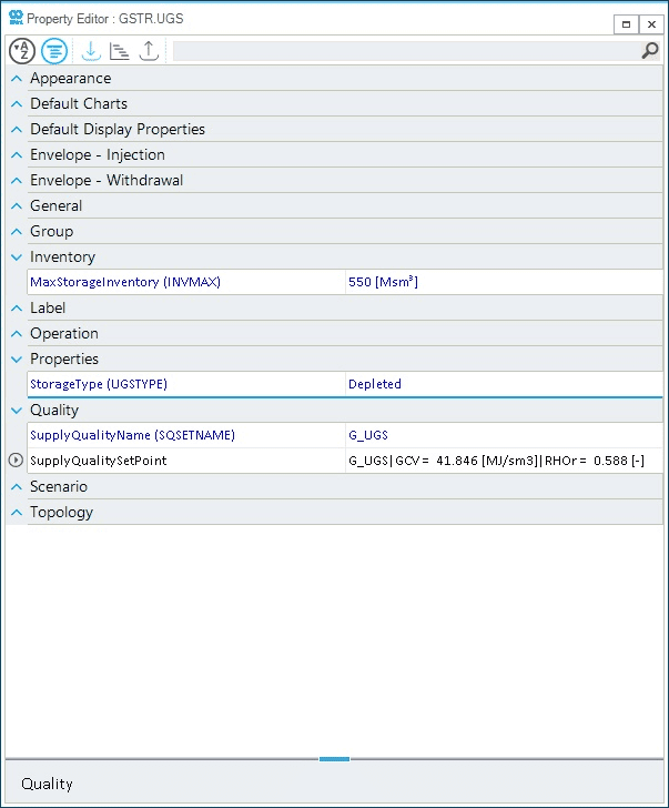
The working gas volume of a gas storage can be set by specifying the MaxStorageInventory property (INVMAX). This specify the upper boundary for the gas storage, while the actual inventory level is determine as part of the solution of a hydraulic scenario. In the example of Figure 4, INVMAX is set to 550 Msm3.
Furthermore, the type of gas storage can be specified using the StorageType property (UGSTYPE). Valid options are: depleted, salt and aquifer. This is a cosmetic attribute, not influencing the mathematical description of the object.
Finally, the quality of the gas stream provided by the gas storage can be selected and assigned with the option SupplyQualityName (SQSETNAME). A drop-down list shows all available gas qualities defined in the network. And the option SupplyQualitySetPoint allows to quickly access all relevant properties of the selected gas quality.
5. Topology and Location
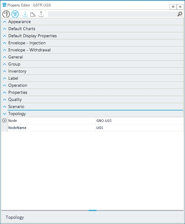
The topology section allows to quickly change the node to which the external is associated. From the drop-down list of the property NodeName a list of valid nodes is presented, and the user can select a different node (Figure 5).
The location of the storage is determined by the location of the node the external is associated to. It cannot be changed in the property editor after selecting the storage object.
6. Operation status and scenario
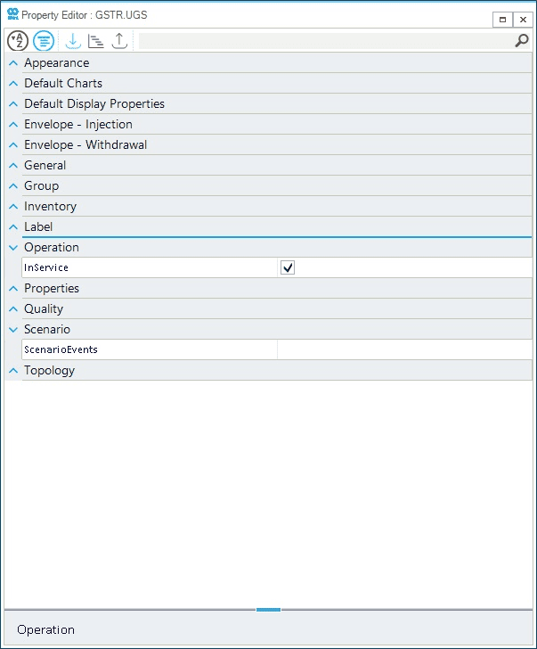
The operational status of a gas storage can be changed globally by setting the property InService on (ticked) or off (not ticked) (Figure 6). This is different from setting the gas storage off using an event in a scenario.
The list of events, implemented in the current scenario, associated to the gas storage is accessible through the option ScenarioEvents under the section Scenario. This is an alternative way to check all events for the object outside the Table GEVT.
7. Default charts and group
The user can create ad hoc charts to describe properties and behavior of a gas storage via the default charts section of the project settings. The list of such charts is reported in the section "Default Charts" for a gas storage object (Figure 7). The user can read the plot command, but for editing it is necessary to open the project’s settings.
Similarly, if the gas storage is part of one or more groups, the properties section "Group" provides a list describing the groups. As for charts, any editing is carried out at object and node level.