Import Network Data in Shapefile Format
This guide provides step-by-step instructions on how to import data saved in shapefile format to create a network in SAInt. The shapefile format is one of the most common geospatial vector data formats and it can be managed by any Geographic Information System (GIS) software. Originally developed by Esri for its commercial product ArcView 2.0 in 1994, the shapefile is a simple format able to store primitive geometrical data types of points, lines, and polygons, with alphanumeric attributes.
While the term "shapefile" is quite common, a "shapefile" is actually a set of several files. Three individual files are mandatory to store the core data: a file for the geometry with extension .shp, a file with the attributes with extension .dbf (a dBase III format), and a file for indexing objects with extension .shx.
|
It is strongly recommended to check the units of measure set for the option |
1. Shapefile data model
SAInt requires the user to prepare the network data using a specific data model. Fluid pipelines or electric lines must be saved in a shapefile using polylines. Because SAInt does not perform any geometric or topological checking (except for removing lines of length equal to zero), the input data must be verified before starting the import wizard. Common errors, like over- or under-shooting, overlapping lines, and crossing segments, must be assessed and addressed. All other facilities must be described by points, with a shapefile for each type of facility. All shapefiles must be in the same projected coordinate system, as SAInt cannot perform coordinate systems conversion during the import process.
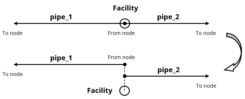
Furthermore, the topological structure of the data must follow some simple rules. Figure 1 shows an example. Any linear object (i.e., a pipeline or an electric line) is geometrically a polyline with a "From node" and "To node"" and other vertices in between. To be connected two polylines must have overlapping nodes, like "pipe_1" and "pipe_2" share their "From node" nodes. A SAInt external is modeled by a point overlapping a line node. Any other branch, except pipelines and electric lines, is modeled by points (either the starting or ending point) overlapping existing lines nodes. In the figure we have two linear elements with a total of three nodes, and an external.
2. The shapefile import wizard
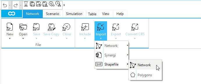
SAInt has a dedicated wizard to guide the user through the different steps to import network data in shapefile format. You can launch the wizard from the "Import" button of the "Network" tab, and then select "Shapefile" and "Network" (Figure 2).
The steps of the wizard are the following:
- STEP 1
-
In the "Welcome" window the user must select the type of network to import. As to the present release, SAInt manages gas and electric networks.
- STEP 2
-
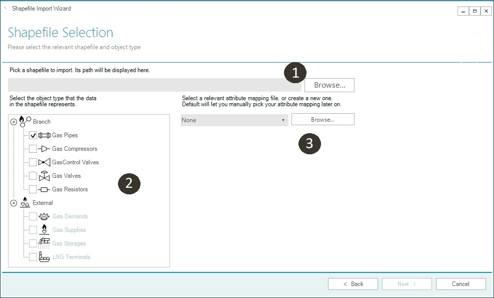
In the "Shapefile Selection" window the user must specify location and name of the
*.shppart of the shapefile to import (❶ in Figure 3), the type of object by ticking next to the object icon of interest (❷) and, optionally, can select a mapping file previously saved during another import session (❸). To properly import data, please start by selecting gas or electric lines first, and after successfully loading them, import all remaining facilities one at a time. Note that SAInt does not allow the selection of multiple items at the same time.
- STEP 3
-
In the "Shapefile Data" window a preview of the attributes table of the selected shapefile is presented. This step facilitates a simple quality check of the data to be imported.
- STEP 4
-
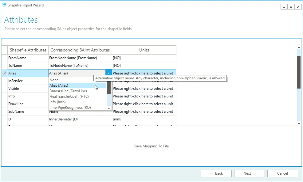
In the "Attributes" window the user can map the attributes stored in the
*.dbffile of the selected shapefile with the relevant base properties of the selected SAInt’s objects. Default units will be selected once the association is confirmed. The user can change the proposed unit. SAInt does not perform an in-depth check of the provided values. The user must make sure that the data are correct. It is possible to save the mapping for future use in a*.samfASCII file (Figure 4).
*.dbf file and the properties of the selected network object of SAInt.- STEP 5
-
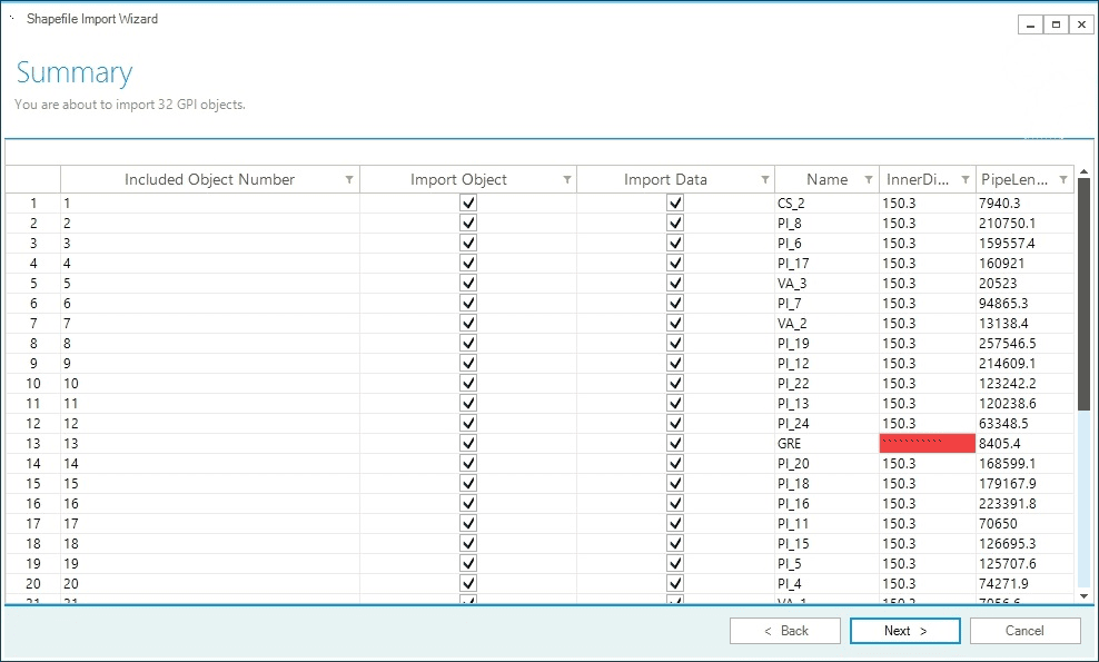
In the "Summary" window the user can inspect a preview of the mapping and select which objects to import ("Import Object", Figure 5). The user can also decide to import only the geometry and drop the associated attributes ("Import Data"), preferring in this way to use SAInt’s default values. Anyway, all cells in red are changed to default values. The total number of objects to be imported is also reported.
- STEP 6
-
In the "Almost Done!" window, the user is informed that by clicking Finish the data will be loaded and the network created. Depending on the amount of data, the process may take some time.
- STEP 7
-
If the procedure is not successful, the user is informed with an error message. SAInt will not try to debug the error, and the user needs to inspect the input data for possible issues. If the procedure is successful, the user is either asked to specify the name and location of the newly generated network when starting with an empty project, or a pop-up window appears indicating the name of the network, the total number of nodes, branches, and externals imported.
- STEP 8
-
The last step of the wizard asks if there is a need to import other data. By selecting "No", the procedure is stopped and the user is redirected to the main window of SAInt. By selecting Yes, the user is presented again with the "Welcome" window of STEP 1 and the procedure starts over.
3. General remarks
Importing shapefiles allows for transferring in SAInt, in a quick and easy way, a lot of data to speed up model development. The user must, anyway, take into consideration the following aspects:
-
SAInt can import only 2D shapefiles. To transfer the height of a node, it is necessary to use a "Parameter" import file.
-
Make sure that the imported figures have the same units of measure as specified in the mapping of the attributes or the ones used in the project by SAInt. The templates have for each numerical property a second column to store the unit of measure. All values in a column must have the same unit of measure. SAInt does not read the details of a certain unit of measure saved in the shapefile.
-
The user may manually intervene to properly connect certain facilities to fluid pipelines or electric lines. All branch objects different from fluid pipelines or electric lines can take advantage of the
FromNameandToNamefields in the shapefile templates to specify the name of the start and end node to which the object is linked. If missing, SAInt will select the nearest starting node based on the location of the starting point defining the object in the shapefile. The ending is left free and will require manual intervention. If the starting point is not near a node, the nearest vertex will be used and transformed into a node (i.e., the associated linear element will be split at that new node). -
If more externals are associated with the same node, there must be overlapping points in the shapefile one for each external.
-
In the section for the project, it is possible to tune two criteria used to simplify complex polylines. It is possible to specify the minimum polyline length (default is 1 cm / 0.394 inch) and the minimum polyline angle (default is 5 degrees). Nodes are not modified. We recommend performing topological and geometric simplification before importing the data. SAInt needs to be further optimized for such tasks. The overall process could be very slow, and the final result may need to be more optimal.