Connect Two Nodes in a Network
This guide shows how to link two nodes in a network to modify its topology by either adding a new branch or by joining the nodes. We demonstrate the two approaches using a simple network composed of two gas pipelines as an example, but the same methods apply to any energy network and branch objects.
1. Use a new branch
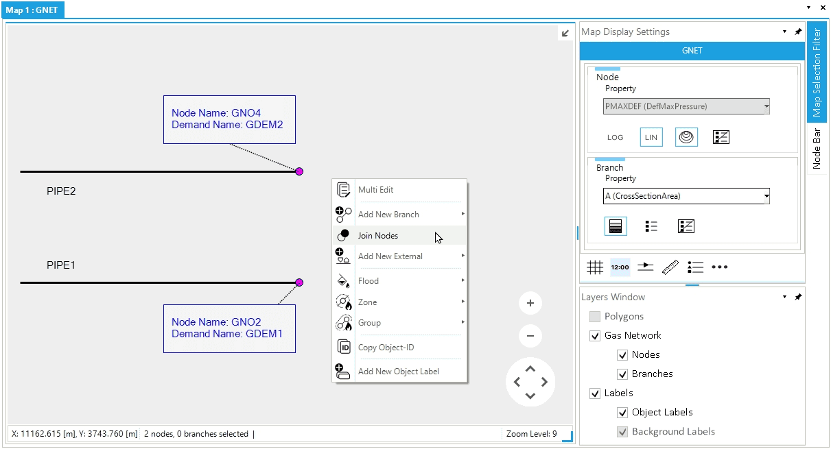
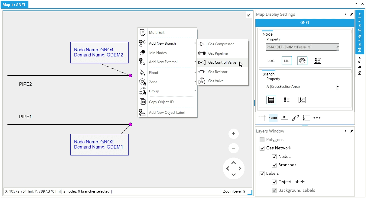
Let’s assume to have two gas pipelines named PIPE1 and PIPE2. Each pipe has a gas demand external associated with one node, as in Figure 1. To connect the two pipelines, we can link node GNO.GNO2 to node GNO.GNO4 by adding a new branch. For this example, we use a control valve.
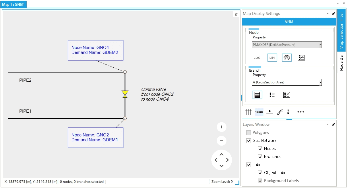
Proceed by selecting in the map view first node GNO.GNO2 and after node GNO.GNO4. Now, right-click, and from the context menu, select (Figure 1). A new control valve is added respecting the direction of flow defined by choosing as starting node GNO.GNO2 and as ending node GNO.GNO4 (Figure 2).
With this method, we increase the number of objects in the network, and we use a branch to create a physical connection between two nodes and all associated externals. The total number of nodes and externals is unchanged, but we add a new branch.
After a branch is created, the FromNode and ToNode properties can be changed to edit the branch’s direction and/or topology if needed (see Edit object’s node Network Topology).
2. Join the nodes
Let’s assume to have two gas pipelines named PIPE1 and PIPE2. Each pipe has a gas demand external associated with one node (Figure 3). To connect the two pipelines, we can join node GNO.GNO2 to node GNO.GNO4.
Proceed by selecting in the map view first node GNO.GNO2 and after node GNO.GNO4. Now, right-click, and from the context, menu select Join Nodes (Figure 3). The user is informed that the requested action will permanently deleted the second node selected (i.e., "Object GNO.GNO4 will be deleted", Figure 4). Proceed by selecting Yes.
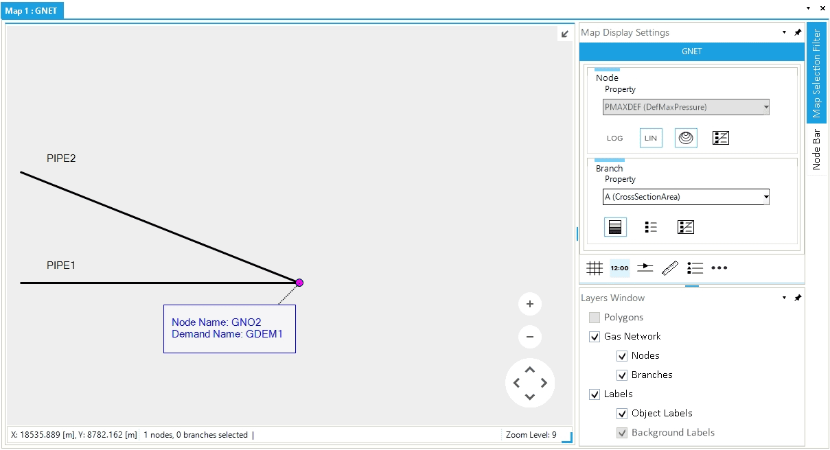
The final result is shown in Figure 5 where the geometry of PIPE2 has changed, and the pipeline shares a physical connection to node GNO.GNO2.
With this method, we decrease the number of objects in the network, and we modify the physical connections between the two pipelines. We start with four nodes and two externals. We end with three nodes and one external. The joined node and all associated externals are removed. The geometry has also changed. The object PIPE2 is now modified and its LGEO property has increased.
|
A nodes join operation always removes from the network the last selected node and all its externals. |