Gas Objects
This section presents an in-depth description of all objects available in SAInt to develop a gas network model. Figure 1 shows the hierarchy and the parent-child relationships between base objects. Table 1 gives a quick and short description of the base objects.
For example, the top level base object in a gas network model is the "Gas Network" object GNET. A gas network contains many other different base objects, such as, for example, gas nodes GNO or gas branches GBR. GNET is the parent, and GNO or GBR is a child. A gas network object has no parents, but only children. A gas component object GCMP cannot be a parent, but only a child. See the schematic below for a visual representation of the complete hierarchical object structure for a gas network model in SAInt.

| Icon | ObjType | Display Name | Description |
|---|---|---|---|
|
|
Gas Network |
Models the characteristics and interactions of facilities and/or components of a gas network. Serves as a container for all objects in the gas network |
|
|
Gas Sub |
Models a subset of nodes, branches, and gas externals of an gas network. A gas sub is branch-oriented, i.e., only gas branches can be assigned to a gas sub, and every gas branch belongs to only one gas sub |
|
|
Gas Zone |
Models a subset of nodes, branches, and externals of a gas network. A gas zone is node-oriented, i.e., only gas nodes can be assigned to a gas zone, and every gas node belongs to only one gas zone |
|
|
Gas Group |
Models a subset of different objects in a gas network. Except for the gas network, subs, and zones, any gas object can be added to a gas group. In contrast to gas subs and zones, gas groups do not follow any specific assignment rules. Thus, a gas object can be part of multiple gas groups |
|
|
Gas Node |
Models a physical or virtual location in the gas network where gas can be injected or extracted through externals (gas demand, supply, storage, etc.) |
|
|
Gas Pipeline |
Models the transport of gas between two distant locations |
|
|
Gas Compressor |
Models the increase of inlet pressure to a higher outlet pressure to ensure continuous transport and delivery of gas to customers at the contracted nominations and delivery pressures |
|
|
Gas Control Valve |
Models the reduction of inlet pressure to lower outlet pressure or the control of gas flow to a downstream network |
|
|
Gas Valve |
Models a valve station, which is used to route the gas stream and shut down sections of the network for maintenance or in case of a disruption. |
|
|
Gas Resistor |
Models passive devices that cause a local pressure drop, such as meters inlet piping, scrubbers, coolers, heaters, etc |
|
|
Gas Supply |
Models the injection of gas at a node |
|
|
Gas Demand |
Models the consumption of gas at a node |
|
|
Gas Storage |
Models the withdrawal and injection of gas from/into the storage inventory of an (underground) gas storage facility |
|
|
LNG terminal |
Models the arrival of LNG-vessels and the discharge, storage, regasification, and injection of liquefied natural gas in an LNG regasification terminal |
|
|
Gas Quality |
Models the thermo dynamic properties (gross/net calorific value, relative density, etc.) and the mixtures of different gas molecules (gas components) flowing through the network |
|
|
Gas Component |
Models the thermo dynamic properties (gross/net calorific value, relative density, etc.) of a gas molecule included in the gas mixture |
|
|
Gas Component Usage |
Models the molar percentage of mixture of a gas component included in a gas quality |


1. Gas network (GNET)
A gas network object is the top parent object in any model of a gas system in SAInt (Figure 1). A gas network object is modeled as a directed graph consisting of a set of gas nodes, branches, and externals that are connected with one another. A gas network contains a description of all geometric, topological, and relational information, as well as all network child objects and their static properties that do not change during the execution of a simulation (e.g., the length and the diameter of a gas pipeline).
The "nodes" of a gas network are objects that identify either junctions among the network branches or physical points where gas can be supplied to or withdrawn from the system.
The "branches" of a gas network are objects that establish how nodes and externals are connected and can passively (e.g., with gas pipelines) or actively (e.g., with gas compressor stations or control valves) modify the state of the gas that flows through them. Branches of a gas network are "pipelines", "compressor stations", "control valves", "valves", and "resistors".
The "externals" of a gas network represent objects supplying or withdrawing gas from the system. Externals of a gas network are "supplies", "demands", "storages", and "LNG terminals".
A gas network also contains further gas-specific objects like "gas qualities", and "gas components".
Scenario events define a change in the settings of a gas network object during the execution of a scenario. Gas network events can be used to customize the network and simulation settings and to compare the effect of different assumptions across simulation scenarios. The following list describes the scenario events available for a network object.
-
Intro
-
derived-result
-
event-default
-
event-value
-
net-input
-
net-read-only
-
event
Summaries for the properties and the events of GNET.
| Extension | Description | UnitType |
|---|---|---|
FB |
Flow balance |
|
QNS |
Difference between flow rate set point and actual flow rate |
|
INV |
Total available storage inventory |
|
LP |
Total linepack |
|
BAL |
Mass Conservation Equation |
|
POWDMAX |
Maximum driver power |
|
QMAX |
Maximum branch flow |
|
VMAX |
Maximum velocity |
|
PMAX |
Maximum pressure |
|
TMAX |
Maximum temperature |
|
POWDMIN |
Minimum driver power |
|
QMIN |
Minimum branch flow |
|
VMIN |
Minimum velocity |
|
PMIN |
Minimum pressure |
|
TMIN |
Minimum temperature |
|
PNS |
Difference between scheduled thermal flow and actual thermal flow |
|
POWD |
Total driver power |
|
QIN |
Total inflow |
|
QOUT |
Total outflow |
|
POWS |
Total shaft power |
| Extension | Description | UnitType |
|---|---|---|
TAMBDEF |
Default ambient temperature |
| Extension | Description | UnitType |
|---|---|---|
TAMB |
Ambient temperature |
|
LPREF |
Reference line pack for comparing results |
| Extension | Description | UnitType |
|---|---|---|
PAMB |
Ambient pressure |
|
Pz_b |
Base pressure for custom compressibility factor equation: Z(P.bar) = 1 + Z_1 * P.bar + Z_2 * ((P.bar - Pz_b.bar) ^2 - Pz_b.bar ^2) |
|
ZEQN |
Equation for computing compressibility factor |
|
Constant |
Constant Value |
|
Constant2 |
Constant Value |
|
Constant3 |
Constant Value |
|
CRSType |
Network coordinate reference system for the node locations |
|
LAMEQN |
Equation for computing friction factor |
|
Info |
Information related to the network model. Any character, including non-alphanumeric, is allowed |
|
Info2 |
Information entered for the object. Any character, including non-alphanumeric, is allowed |
|
Info3 |
Information entered for the object. Any character, including non-alphanumeric, is allowed |
|
Kappa |
Isentropic exponent, i.e. ratio between isobaric and isochoric heat capacity |
|
Z_1 |
Coefficient of linear term in custom compressibility factor equation: Z(P.bar) = 1 + Z_1 * P.bar + Z_2 * ((P.bar - Pz_b.bar) ^2 - Pz_b.bar ^2) |
|
Z_2 |
Coefficient of quadratic term in custom compressibility factor equation: Z(P.bar) = 1 + Z_1 * P.bar + Z_2 * ((P.bar - Pz_b.bar) ^2 - Pz_b.bar ^2) |
|
Pn |
Pressure at reference condition |
|
Tn |
Reference temperature |
|
VarPAMB |
Consider ambient pressure dependence on the elevation |
|
VISC |
Dynamic viscosity used for calculating the friction factor |
| Extension | Description | UnitType |
|---|---|---|
DMAX |
Maximum branch inner diameter |
|
DMIN |
Minimum branch inner diameter |
|
Name |
Name of the network model. Permitted characters are letters, numbers, and underscore ("_"). The name should start with a letter. |
|
NetType |
Network Type |
|
NUMBR |
Number of branches in the network, sub, zone or group |
|
NUMXT |
Number of externals in the network, sub, zone or group |
|
NUMLOOP |
Number of closed loops in the network, sub, zone or group |
|
NUMNO |
Number of nodes in the network, sub, zone or group |
|
ObjType |
Object Type |
|
UID |
Unique identifier for the object which cannot be changed during the lifetime of the object |
| Parameter | Type | Description | UnitType |
|---|---|---|---|
H |
IniSetting |
Constant elevation. Minimum: 0. |
|
HTON |
IniSetting |
Turn on temperature tracking. |
|
LAM |
IniSetting |
Constant friction factor. Minimum: 0. |
|
LPREF |
Reference |
Reference linepack. Minimum: 0. |
|
QTOFF |
IniSetting |
Turn off gas quality tracking. |
|
RO |
IniSetting |
Constant roughness. Minimum: 0. |
|
TAMB |
Ambient |
Ambient temperature. Minimum: 0. |
|
Z |
IniSetting |
Constant compressibility factor. Minimum: 0. |
An overview of a supply trace analysis is available from the "Result Properties" section of the Property Editor under "Supply Trance Overview". The results are organized in a table providing the proportion of a certain supply source (by columns) covering the demand of a GDEM (by rows). The user can access the table by clicking on the three dots of the entry "SupplyTraceOverview" in the Property Editor. By right-clicking on the table, you can access a context menu that allows you to export the table in text, comma-separated, or Excel format.
|
When using the AGA8DC92 or the GERG2008 as the equation model for the compressibility factor, SAInt checks for a valid range of values for the selected gas mixture, and, in case, informs the user of a violation leading to a lack in convergence. A change in the gas mixture is required to solve the problem. |
2. Gas network container
The child objects of a network can be grouped into the following subsets, also referred to as "containers": sub, zone, and group. These arrangements can be used to define relevant information for a network, or they can simply be used to conveniently aggregate outputs of a scenario.
2.1. Gas sub (GSUB)
A sub (also referred to as sub-network or sub-system) is a subset of nodes, branches, and externals of a network. A sub is branch-oriented, i.e., only branches can be assigned to a sub, and every branch belongs to only one sub. The FromNode and ToNode of a branch, as well as the externals connected to these two nodes, are implicitly added to the sub. Thus, nodes connecting branches of different subs and the externals connected to these nodes are always included in multiple subs. But all properties of a sub are determined by the branches belonging to it.
-
Intro
-
derived-result
-
event-value
-
net-input
-
net-read-only
-
event
Summaries for the properties and the events of GSUB.
| Extension | Description | UnitType |
|---|---|---|
FB |
Flow balance |
|
QNS |
Difference between flow rate set point and actual flow rate |
|
INV |
Total available storage inventory |
|
LP |
Total linepack |
|
BAL |
Mass Conservation Equation |
|
POWDMAX |
Maximum driver power |
|
QMAX |
Maximum branch flow |
|
VMAX |
Maximum velocity |
|
PMAX |
Maximum pressure |
|
TMAX |
Maximum temperature |
|
POWDMIN |
Minimum driver power |
|
QMIN |
Minimum branch flow |
|
VMIN |
Minimum velocity |
|
PMIN |
Minimum pressure |
|
TMIN |
Minimum temperature |
|
PNS |
Difference between scheduled thermal flow and actual thermal flow |
|
POWD |
Total driver power |
|
QIN |
Total inflow |
|
QOUT |
Total outflow |
|
POWS |
Total shaft power |
| Extension | Description | UnitType |
|---|---|---|
TAMB |
Ambient temperature |
| Extension | Description | UnitType |
|---|---|---|
Constant |
Constant Value |
|
Constant2 |
Constant Value |
|
Constant3 |
Constant Value |
|
Info |
Information entered for the object. Any character, including non-alphanumeric, is allowed |
|
Info2 |
Information entered for the object. Any character, including non-alphanumeric, is allowed |
|
Info3 |
Information entered for the object. Any character, including non-alphanumeric, is allowed |
|
Name |
Object Name. Permitted characters are letters, numbers, and underscore ("_"). The name should start with a letter. The name should be unique for each object type. |
| Extension | Description | UnitType |
|---|---|---|
DMAX |
Maximum branch inner diameter |
|
DMIN |
Minimum branch inner diameter |
|
NetType |
Network Type |
|
NUMBR |
Number of branches in the network, sub, zone or group |
|
NUMXT |
Number of externals in the network, sub, zone or group |
|
NUMLOOP |
Number of closed loops in the network, sub, zone or group |
|
NUMNO |
Number of nodes in the network, sub, zone or group |
|
ObjType |
Object Type |
|
UID |
Unique identifier for the object which cannot be changed during the lifetime of the object |
| Parameter | Type | Description | UnitType |
|---|---|---|---|
TAMB |
Ambient |
Ambient temperature. Minimum: 0. |
2.2. Gas zone (GZN)
A zone is a subset of nodes, branches, and externals of a gas network. Differently from subs, zones are node-oriented, i.e., only nodes can be assigned to a zone, and every node belongs to one zone. Branches with a FromNode and ToNode belonging to the same zone are implicitly added to the corresponding zone. In contrast, branches with a FromNode and ToNode belonging to two different zones do not belong to any zone. Externals are also implicitly added to the zone of the node they are connected to. But all properties of a zone are determined by the nodes belonging to it.
-
Intro
-
derived-result
-
net-input
-
net-read-only
Summaries for the properties and the events of GZN.
| Extension | Description | UnitType |
|---|---|---|
FB |
Flow balance |
|
QNS |
Difference between flow rate set point and actual flow rate |
|
INV |
Total available storage inventory |
|
LP |
Total linepack |
|
BAL |
Mass Conservation Equation |
|
POWDMAX |
Maximum driver power |
|
QMAX |
Maximum branch flow |
|
VMAX |
Maximum velocity |
|
PMAX |
Maximum pressure |
|
TMAX |
Maximum temperature |
|
POWDMIN |
Minimum driver power |
|
QMIN |
Minimum branch flow |
|
VMIN |
Minimum velocity |
|
PMIN |
Minimum pressure |
|
TMIN |
Minimum temperature |
|
PNS |
Difference between scheduled thermal flow and actual thermal flow |
|
POWD |
Total driver power |
|
QIN |
Total inflow |
|
QOUT |
Total outflow |
|
POWS |
Total shaft power |
| Extension | Description | UnitType |
|---|---|---|
Constant |
Constant Value |
|
Constant2 |
Constant Value |
|
Constant3 |
Constant Value |
|
Info |
Information entered for the object. Any character, including non-alphanumeric, is allowed |
|
Info2 |
Information entered for the object. Any character, including non-alphanumeric, is allowed |
|
Info3 |
Information entered for the object. Any character, including non-alphanumeric, is allowed |
|
Name |
Object Name. Permitted characters are letters, numbers, and underscore ("_"). The name should start with a letter. The name should be unique for each object type. |
| Extension | Description | UnitType |
|---|---|---|
DMAX |
Maximum branch inner diameter |
|
DMIN |
Minimum branch inner diameter |
|
NetType |
Network Type |
|
NUMBR |
Number of branches in the network, sub, zone or group |
|
NUMXT |
Number of externals in the network, sub, zone or group |
|
NUMLOOP |
Number of closed loops in the network, sub, zone or group |
|
NUMNO |
Number of nodes in the network, sub, zone or group |
|
ObjType |
Object Type |
|
UID |
Unique identifier for the object which cannot be changed during the lifetime of the object |
2.3. Gas group (GGRP)
A group is a subset of different child object types (e.g., nodes, branches, externals, etc.) of the whole network. In contrast to subs and zones, groups do not follow any specific assignment rules. Thus, a child object can be assigned to multiple groups, and a group can have as many child objects assigned to it as there are child objects in the network.
-
Intro
-
derived-result
-
net-input
-
net-read-only
Summaries for the properties and the events of GGRP.
| Extension | Description | UnitType |
|---|---|---|
FB |
Flow balance |
|
QNS |
Difference between flow rate set point and actual flow rate |
|
INV |
Total available storage inventory |
|
LP |
Total linepack |
|
BAL |
Mass Conservation Equation |
|
POWDMAX |
Maximum driver power |
|
QMAX |
Maximum branch flow |
|
VMAX |
Maximum velocity |
|
PMAX |
Maximum pressure |
|
TMAX |
Maximum temperature |
|
POWDMIN |
Minimum driver power |
|
QMIN |
Minimum branch flow |
|
VMIN |
Minimum velocity |
|
PMIN |
Minimum pressure |
|
TMIN |
Minimum temperature |
|
PNS |
Difference between scheduled thermal flow and actual thermal flow |
|
POWD |
Total driver power |
|
QIN |
Total inflow |
|
QOUT |
Total outflow |
|
POWS |
Total shaft power |
| Extension | Description | UnitType |
|---|---|---|
Constant |
Constant Value |
|
Constant2 |
Constant Value |
|
Constant3 |
Constant Value |
|
Info |
Information entered for the object. Any character, including non-alphanumeric, is allowed |
|
Info2 |
Information entered for the object. Any character, including non-alphanumeric, is allowed |
|
Info3 |
Information entered for the object. Any character, including non-alphanumeric, is allowed |
|
Name |
Object Name. Permitted characters are letters, numbers, and underscore ("_"). The name should start with a letter. The name should be unique for each object type. |
| Extension | Description | UnitType |
|---|---|---|
DMAX |
Maximum branch inner diameter |
|
DMIN |
Minimum branch inner diameter |
|
NetType |
Network Type |
|
NUMCNSTR |
Number of branches in the network, sub, zone or group |
|
NUMBR |
Number of branches in the network, sub, zone or group |
|
NUMXT |
Number of externals in the network, sub, zone or group |
|
NUMLOOP |
Number of closed loops in the network, sub, zone or group |
|
NUMNO |
Number of nodes in the network, sub, zone or group |
|
ObjType |
Object Type |
|
UID |
Unique identifier for the object which cannot be changed during the lifetime of the object |
3. Gas node (GNO)
Nodes represent objects describing a junction among two or more gas branches, as well as a location in the gas network where gas can be injected or extracted through externals (e.g., demand, supply, etc.).
-
Intro
-
base-result
-
derived-event-value
-
derived-result
-
event-default
-
event-value
-
net-input
-
net-read-only
-
event
Summaries for the properties and the events of GNO.
| Extension | Description | UnitType |
|---|---|---|
P |
Pressure at nodes |
|
T |
Temperature at nodes |
| Extension | Description | UnitType |
|---|---|---|
TAMB |
Ambient temperature |
| Extension | Description | UnitType |
|---|---|---|
RHO |
Gas density |
|
QNS |
Difference between flow rate set point and actual flow rate |
|
Z |
Compressibility at nodes |
|
Q |
In- or Outflow at nodes |
|
c |
Speed of sound at nodes |
|
QVOL |
Volumetric in- or outflow at nodes |
|
TQ |
Thermal flow |
|
PNS |
Difference between scheduled thermal flow and actual thermal flow |
| Extension | Description | UnitType |
|---|---|---|
PMAXDEF |
Default maximum pressure |
|
PMAXPRCDEF |
Default penalty price for maximum pressure. If PMAXPRCDEF > 0, P will be limited to PMAX. if PMAXPRCDEF = -inf, simulation will cease upon exceeding PMAX. if PMAXPRCDEF = 0, exceeding PMAX will result in a warning |
|
PMINDEF |
Default minimum pressure |
|
PMINPRCDEF |
Default penalty price for minimum pressure. If PMINPRCDEF > 0, P will be limited to PMIN. If PMINPRCDEF = -inf, simulation will cease when P falls below PMIN. If PMINPRCDEF = 0, going below PMIN will result in a warning |
|
InServiceDef |
Indicates if an object is considered or disregarded in the execution of a scenario. Externals connected to the node inherit the "inService" status of the node |
| Extension | Description | UnitType |
|---|---|---|
InService |
Indicates if an object is considered or disregarded in the execution of a scenario. Externals connected to the node inherit the "inService" status of the node |
|
PMAX |
Maximum pressure constraint |
|
PMAXPRC |
Penalty price for maximum pressure. If PMAXPRC > 0, P will be limited to PMAX. if PMAXPRC = -inf, simulation will cease upon exceeding PMAX. if PMAXPRC = 0, exceeding PMAX will result in a warning |
|
PMIN |
Minimum pressure constraint |
|
PMINPRC |
Penalty price for minimum pressure. If PMINPRC > 0, P will be limited to PMIN. If PMINPRC = -inf, simulation will cease when P falls below PMIN. If PMINPRC = 0, going below PMIN will result in a warning |
|
QREF |
Reference flow rate for comparing results |
|
PREF |
Reference nodal pressure for comparing results |
|
TREF |
Reference nodal temperature for comparing results |
| Extension | Description | UnitType |
|---|---|---|
Alias |
Alternative object name. Any character, including non-alphanumeric, is allowed |
|
Constant |
Constant Value |
|
Constant2 |
Constant Value |
|
Constant3 |
Constant Value |
|
H |
Elevation |
|
Info |
Information entered for the object. Any character, including non-alphanumeric, is allowed |
|
Info2 |
Information entered for the object. Any character, including non-alphanumeric, is allowed |
|
Info3 |
Information entered for the object. Any character, including non-alphanumeric, is allowed |
|
Name |
Object Name. Permitted characters are letters, numbers, and underscore ("_"). The name should start with a letter. The name should be unique for each object type. |
|
Visible |
If true, the object symbol will be visible in maps |
|
X |
Cartesian X or Longitude coordinate for visualizing the node in the map. Externals assigned to the node are not displayed |
|
Y |
Cartesian Y or Latitude coordinate for visualizing the node in the map. Externals assigned to the node are not displayed |
|
ZoneName |
ZoneName of the zone the node belongs to |
| Extension | Description | UnitType |
|---|---|---|
NetType |
Network Type |
|
ID |
Object Identification |
|
ObjType |
Object Type |
|
UID |
Unique identifier for the object which cannot be changed during the lifetime of the object |
| Parameter | Type | Description | UnitType |
|---|---|---|---|
OFF |
ControlSetPoint |
Turn off connected externals. |
|
PMAX |
Constraint |
Maximum nodal pressure. Minimum: 0. |
|
PMAXPRC |
PenaltyPrice |
Penalty price for maximum nodal pressure. |
|
PMIN |
Constraint |
Minimum nodal pressure. Minimum: 0. |
|
PMINPRC |
PenaltyPrice |
Penalty price for minimum nodal pressure. |
|
PREF |
Reference |
Reference nodal pressure. Minimum: 0. |
|
QREF |
Reference |
Reference flow rate. |
|
TREF |
Reference |
Reference nodal temperature. Minimum: 0. |
4. Gas branch (GBR)
A branch is a general type of object which describes a generic connection between two gas nodes. Different types of branches exist in SAInt and the following sections provides more details on each of them.
4.1. Gas pipeline (GPI)
A gas pipeline is an object which models the transport of gas between two locations and connects two nodes. Gas pipelines (also referred to as pipes) are passive branches, as no active control can be imposed over them. Gas flowing along a gas pipeline is subject to pressure drops due to friction. The magnitude of the pressure drop depends on the flow rate, the composition, the thermodynamic state of the gas (pressure, temperature), and on the properties of the pipelines (diameter, length, internal roughness).
-
Intro
-
base-result
-
derived-result
-
event-default
-
event-value
-
net-input
-
net-read-only
-
event
Summaries for the properties and the events of GPI.
| Extension | Description | UnitType |
|---|---|---|
T |
Average temperature in the pipeline |
|
Q |
Mass flow rate in the pipeline |
| Extension | Description | UnitType |
|---|---|---|
Z |
Average compressibility in the pipeline |
|
P |
Average pressure in the pipeline |
|
c |
Average speed of sound in the pipeline |
|
V |
Flow velocity |
|
LAM |
Friction factor |
|
RHOI |
Inlet density |
|
VI |
Flow velocity at the inlet of the branch |
|
PI |
Inlet node pressure |
|
TI |
Inlet temperature |
|
QVOLI |
Volumetric flow rate at the inlet of the branch |
|
LP |
Total line pack in pipeline |
|
RHOO |
Outlet density |
|
VO |
Flow velocity at the outlet of the branch |
|
PO |
Pressure of outlet node |
|
TO |
Outlet temperature |
|
QVOLO |
Volumetric flow rate at the outlet of the branch |
|
QVOL |
Volumetric flow in the pipeline |
|
PD |
Pressure difference between outlet and inlet in flow direction |
|
PR |
Pressure ratio between outlet and inlet node |
|
RF |
Resistance factor |
|
REY |
Reynolds number |
|
TRVL |
Average travel time of a particle in pipeline |
| Extension | Description | UnitType |
|---|---|---|
InServiceDef |
Indicates if an object is considered or disregarded in the execution of a scenario. Externals connected to the node inherit the "inService" status of the node |
| Extension | Description | UnitType |
|---|---|---|
TAMB |
Ambient temperature |
|
InService |
Indicates if an object is considered or disregarded in the execution of a scenario. Externals connected to the node inherit the "inService" status of the node |
|
QREF |
Reference flow rate for comparing results |
| Extension | Description | UnitType |
|---|---|---|
Alias |
Alternative object name. Any character, including non-alphanumeric, is allowed |
|
Constant |
Constant Value |
|
Constant2 |
Constant Value |
|
Constant3 |
Constant Value |
|
DrawLine |
If true, element will be drawn as a straight line and internal points will be neglected |
|
FromName |
Name of FromNode |
|
HTC |
Heat transfer coefficient |
|
Info |
Information entered for the object. Any character, including non-alphanumeric, is allowed |
|
Info2 |
Information entered for the object. Any character, including non-alphanumeric, is allowed |
|
Info3 |
Information entered for the object. Any character, including non-alphanumeric, is allowed |
|
D |
Inner pipe diameter or design diameter of non-pipe branches |
|
RO |
Inner wall roughness of pipeline |
|
Name |
Object Name. Permitted characters are letters, numbers, and underscore ("_"). The name should start with a letter. The name should be unique for each object type. |
|
Eff |
Pipeline efficiency |
|
L |
Pipeline length |
|
SubName |
Sub the branch belongs to |
|
ToName |
Name of ToNode |
|
Visible |
If true, the object symbol will be visible in maps |
|
WTH |
Thickness of the pipe wall |
| Extension | Description | UnitType |
|---|---|---|
A |
Cross sectional area |
|
DH |
Elevation difference between inlet and outlet nodes |
|
LGEO |
Length According to Map Coordinates |
|
ALPHA |
Pipeline inclination |
|
LD |
Difference between actual pipeline length and geographic length |
|
NetType |
Network Type |
|
J |
Number of pipe segments after pipe discretization |
|
ID |
Object Identification |
|
ObjType |
Object Type |
|
DOUT |
Outer pipe diameter, based on the wall thickness and inner diameter |
|
VOL |
Geometric pipe volume |
|
UID |
Unique identifier for the object which cannot be changed during the lifetime of the object |
|
Inlet and outlet-derived properties do not depend on the flow direction but on the drawing direction of the pipeline (i.e., from which start node to which end node). |
4.2. Gas compressor (GCS)
A gas compressor is an object that increases the inlet gas pressure to a higher outlet pressure to ensure continuous transport and delivery of natural gas to its customers at the contracted nominations and delivery pressures. A gas compressor is an active branch connecting two nodes, and it requires an assigned control mode (scenario event) to operate. Gas compressors typically use part of the fuel that they process to produce compression work. In the current release of SAInt, the fuel consumed at a compressor station is not accounted for any flow balance the compressor station contributes to, but it is set apart.
-
Intro
-
base-result
-
derived-event-value
-
derived-result
-
event-default
-
event-value
-
net-input
-
net-read-only
-
event
Summaries for the properties and the events of GCS.
| Extension | Description | UnitType |
|---|---|---|
CTRL |
Control mode of controlled facility |
|
CTRLSET |
Scheduled station control |
|
CTRLSETVAL |
Scheduled station control value |
|
CTRLVAL |
Control set point value |
|
Q |
Mass flow rate in the pipeline |
| Extension | Description | UnitType |
|---|---|---|
TAMB |
Ambient temperature |
| Extension | Description | UnitType |
|---|---|---|
HAD |
Adiabatic head |
|
Z |
Inlet compressibility factor |
|
P |
Average pressure in the pipeline |
|
c |
Average speed of sound in the pipeline |
|
POWD |
Driver power |
|
V |
Flow velocity |
|
FUEL |
Required fuel for compression |
|
RHOI |
Inlet density |
|
VI |
Flow velocity at the inlet of the branch |
|
PI |
Inlet node pressure |
|
TI |
Inlet temperature |
|
QVOLI |
Volumetric flow rate at the inlet of the branch |
|
RHOO |
Outlet density |
|
VO |
Flow velocity at the outlet of the branch |
|
PO |
Pressure of outlet node |
|
TO |
Outlet temperature |
|
QVOLO |
Volumetric flow rate at the outlet of the branch |
|
QVOL |
Volumetric flow in the pipeline |
|
PD |
Pressure difference between outlet and inlet in flow direction |
|
PR |
Pressure ratio between outlet and inlet node |
|
POWS |
Shaft power |
| Extension | Description | UnitType |
|---|---|---|
EFFHDEF |
Default average adiabatic efficiency |
|
POWDMAXDEF |
Default maximum driver power |
|
POWDMAXPRCDEF |
Default Penalty price for maximum driver power. If POWDMAXPRC > 0, POWD will be limited to POWDMAX. If POWDMAXPRCDEF = -inf, simulation will cease upon exceeding POWDMAX. If POWDMAXPRCDEF = 0, exceeding POWDMAX will result in a warning |
|
QMAXDEF |
Default maximum flow rate |
|
QMAXPRCDEF |
Default penalty price for maximum flow rate. If QMAXPRCDEF > 0, Q will be limited to QMAX. If QMAXPRCDEF = -inf, simulation will cease upon exceeding QMAX. If QMAXPRCDEF = 0, exceeding QMAX will result in a warning |
|
POMAXDEF |
Default maximum outlet pressure |
|
POMAXPRCDEF |
Default penalty price for maximum outlet pressure. If POMAXPRCDEF > 0, PO will be limited to POMAX. If POMAXPRCDEF = -inf, simulation will cease upon exceeding POMAX. If POMAXPRCDEF = 0, exceeding POMAX will result in a warning |
|
PRMAXDEF |
Default maximum pressure ratio |
|
PRMAXPRCDEF |
Default penalty price for maximum pressure ratio. If PRMAXPRCDEF > 0, PR will be limited to PRMAX. If PRMAXPRCDEF = -inf, simulation will cease upon exceeding PRMAX. If PRMAXPRCDEF = 0, exceeding PRMAX will result in a warning |
|
POWSMAXDEF |
Default maximum shaft power |
|
POWSMAXPRCDEF |
Default penalty price for maximum shaft power. If POWSMAXPRC > 0, POWS will be limited to POWSMAX. If POWSMAXPRCDEF = -inf, simulation will cease upon exceeding POWSMAX. If POWSMAXPRCDEF = 0, exceeding POWSMAX will result in a warning |
|
VMAXDEF |
Default maximum flow velocity |
|
VMAXPRCDEF |
Default penalty price for maximum flow velocity. If VMAXPRCDEF > 0, V will be limited to VMAX. If VMAXPRCDEF = -inf, simulation will cease upon exceeding VMAX. If VMAXPRCDEF = 0, exceeding VMAX will result in a warning |
|
QVOLMAXDEF |
Default maximum volumetric flow rate |
|
QVOLMAXPRCDEF |
Default penalty price for maximum volumetric flow rate. If QVOLMAXPRC > 0, QVOL will be limited to QVOLMAX. If QVOLMAXPRCDEF = -inf, simulation will cease upon exceeding QVOLMAX. If QVOLMAXPRCDEF = 0, exceeding QVOLMAX will result in a warning |
|
EFFMDEF |
Default average driver efficiency |
|
PIMINDEF |
Default minimum inlet pressure |
|
PIMINPRCDEF |
Default penalty price for minimum inlet pressure. If PIMINPRCDEF > 0, PI will be limited to PIMIN. If PIMINPRCDEF = -inf, simulation will cease when PI falls below PIMIN. If PIMINPRCDEF = 0, going below PIMIN will result in a warning |
|
InServiceDef |
Indicates if an object is considered or disregarded in the execution of a scenario. Externals connected to the node inherit the "inService" status of the node |
| Extension | Description | UnitType |
|---|---|---|
EFFH |
Average adiabatic efficiency |
|
InService |
Indicates if an object is considered or disregarded in the execution of a scenario. Externals connected to the node inherit the "inService" status of the node |
|
POWDMAX |
Maximum available driver power |
|
POWDMAXPRC |
Penalty price for maximum driver power. If POWDMAXPRC > 0, POWD will be limited to POWDMAX. If POWDMAXPRC= -inf, simulation will cease upon exceeding POWDMAX. If POWDMAXPRC = 0, exceeding POWDMAX will result in a warning |
|
QMAXPRC |
Penalty price for maximum flow rate. If QMAXPRC > 0, Q will be limited to QMAX. If QMAXPRC = -inf, simulation will cease upon exceeding QMAX. If QMAXPRC = 0, exceeding QMAX will result in a warning |
|
QMAX |
Maximum flow rate |
|
VMAX |
Maximum flow velocity |
|
POMAX |
Maximum outlet pressure constraint |
|
POMAXPRC |
Penalty price for maximum outlet pressure. If POMAXPRC > 0, PO will be limited to POMAX. If POMAXPRC = -inf, simulation will cease upon exceeding POMAX. If POMAXPRC = 0, exceeding POMAX will result in a warning |
|
PRMAX |
Maximum pressure ratio |
|
PRMAXPRC |
Penalty price for maximum pressure ratio. If PRMAXPRC > 0, PR will be limited to PRMAX. If PRMAXPRC = -inf, simulation will cease upon exceeding PRMAX. If PRMAXPRC = 0, exceeding PRMAX will result in a warning |
|
POWSMAX |
Maximum shaft power |
|
POWSMAXPRC |
Penalty price for maximum shaft power. If POWSMAXPRC > 0, POWS will be limited to POWSMAX. If POWSMAXPRC = -inf, simulation will cease upon exceeding POWSMAX. If POWSMAXPRC = 0, exceeding POWSMAX will result in a warning |
|
VMAXPRC |
Penalty price for maximum flow velocity. If VMAXPRC > 0, V will be limited to VMAX. If VMAXPRC = -inf, simulation will cease upon exceeding VMAX. If VMAXPRC = 0, exceeding VMAX will result in a warning |
|
QVOLMAX |
Maximum volumetric flow rate |
|
QVOLMAXPRC |
Penalty price for maximum volumetric flow rate. If QVOLMAXPRC > 0, QVOL will be limited to QVOLMAX. If QVOLMAXPRC = -inf, simulation will cease upon exceeding QVOLMAX. If QVOLMAXPRC=0, exceeding QVOLMAX will result in a warning |
|
EFFM |
Average driver efficiency |
|
PIMIN |
Minimum inlet pressure constraint |
|
PIMINPRC |
Penalty price for minimum inlet pressure. If PIMINPRC > 0, PI will be limited to PIMIN. If PIMINPRC = -inf, simulation will cease when PI falls below PIMIN. If PIMINPRC = 0, going below PIMIN will result in a warning |
|
QREF |
Reference flow rate for comparing results |
| Extension | Description | UnitType |
|---|---|---|
Alias |
Alternative object name. Any character, including non-alphanumeric, is allowed |
|
Constant |
Constant Value |
|
Constant2 |
Constant Value |
|
Constant3 |
Constant Value |
|
DrawLine |
If true, element will be drawn as a straight line and internal points will be neglected |
|
ExtractFuel |
Extract required fuel from inlet node |
|
FromName |
Name of FromNode |
|
Info |
Information entered for the object. Any character, including non-alphanumeric, is allowed |
|
Info2 |
Information entered for the object. Any character, including non-alphanumeric, is allowed |
|
Info3 |
Information entered for the object. Any character, including non-alphanumeric, is allowed |
|
D |
Inner pipe diameter or design diameter of non-pipe branches |
|
Name |
Object Name. Permitted characters are letters, numbers, and underscore ("_"). The name should start with a letter. The name should be unique for each object type. |
|
RemoteName |
Name of gas remote node |
|
SubName |
Sub the branch belongs to |
|
ToName |
Name of ToNode |
|
Visible |
If true, the object symbol will be visible in maps |
| Extension | Description | UnitType |
|---|---|---|
A |
Cross sectional area |
|
DH |
Elevation difference between inlet and outlet nodes |
|
LGEO |
Length According to Map Coordinates |
|
NetType |
Network Type |
|
ID |
Object Identification |
|
ObjType |
Object Type |
|
UID |
Unique identifier for the object which cannot be changed during the lifetime of the object |
| Parameter | Type | Description | UnitType |
|---|---|---|---|
BP |
ControlSetPoint |
Turn station into bypass. |
|
EFFH |
Efficiency |
Average adiabatic efficiency. Minimum: 0. Maximum: 1. |
|
EFFM |
Efficiency |
Average driver efficiency. Minimum: 0. Maximum: 1. |
|
FUELSET |
ControlSetPoint |
Fuel consumption set point. Minimum: 0. |
|
NRBP |
ControlSetPoint |
Turn station into non-return bypass. |
|
OFF |
ControlSetPoint |
Turn off facility, service or object. |
|
PDSET |
ControlSetPoint |
Pressure difference set point. Minimum: 0. |
|
PIMIN |
Constraint |
Minimum inlet pressure. Minimum: 0. |
|
PIMINPRC |
PenaltyPrice |
Penalty price for minimum inlet pressure. |
|
PISET |
ControlSetPoint |
Inlet pressure set point. Minimum: 0. |
|
POMAX |
Constraint |
Maximum outlet pressure. Minimum: 0. |
|
POMAXPRC |
PenaltyPrice |
Penalty price for maximum outlet pressure. |
|
POSET |
ControlSetPoint |
Outlet pressure set point. Minimum: 0. |
|
POWDMAX |
Constraint |
Maximum driver power. Minimum: 0. |
|
POWDMAXPRC |
PenaltyPrice |
Penalty price for maximum driver power. |
|
POWDSET |
ControlSetPoint |
Driver power set point. Minimum: 0. |
|
POWSMAX |
Constraint |
Maximum shaft power. Minimum: 0. |
|
POWSMAXPRC |
PenaltyPrice |
Penalty price for maximum shaft power. |
|
POWSSET |
ControlSetPoint |
Shaft power set point. Minimum: 0. |
|
PREMSET |
ControlSetPoint |
Remote pressure set point. Minimum: 0. |
|
PRMAX |
Constraint |
Maximum pressure ratio. Minimum: 1. Maximum: 5. |
|
PRMAXPRC |
PenaltyPrice |
Penalty price for maximum pressure ratio. |
|
PRSET |
ControlSetPoint |
Pressure ratio set point. Minimum: 1. Maximum: 5. |
|
QMAX |
Constraint |
Maximum flow rate. Minimum: 0. |
|
QMAXPRC |
PenaltyPrice |
Penalty price for maximum flow rate. |
|
QREF |
Reference |
Reference flow rate. |
|
QSET |
ControlSetPoint |
Flow rate set point. Minimum: 0. |
|
QVOLMAX |
Constraint |
Maximum volumetric flow rate. Minimum: 0. |
|
QVOLMAXPRC |
PenaltyPrice |
Penalty price for maximum volumetric flow rate. |
|
QVOLSET |
ControlSetPoint |
Volumetric flow rate set point. Minimum: 0. |
|
R |
ControlSetPoint |
Resistance factor. Minimum: 0. |
|
VMAX |
Constraint |
Maximum flow velocity. Minimum: 0. |
|
VMAXPRC |
PenaltyPrice |
Penalty price for maximum flow velocity. |
|
The fuel consumption of a gas compressor unit is calculated as the ratio between the power input to the driver and the gross calorific value of the gas at the inlet point. Both figures are derived results based on the solution of the simulation time step. |
|
When calculating the driver power See "Network (GNET)" for some reference values for different gas types. |
4.3. Gas resistor (GRE)
A gas resistor is an object describing any passive device that reduces the pressure of the gas flowing across it. A gas resistor can be used to model pressure drops across different objects such as gas meters, coolers, heaters, etc.
-
Intro
-
base-result
-
derived-event-value
-
derived-result
-
event-default
-
event-value
-
net-input
-
net-read-only
-
event
Summaries for the properties and the events of GRE.
| Extension | Description | UnitType |
|---|---|---|
Q |
Mass flow rate in the pipeline |
| Extension | Description | UnitType |
|---|---|---|
TAMB |
Ambient temperature |
| Extension | Description | UnitType |
|---|---|---|
Z |
Inlet compressibility factor |
|
P |
Average pressure in the pipeline |
|
c |
Average speed of sound in the pipeline |
|
V |
Flow velocity |
|
RHOI |
Inlet density |
|
VI |
Flow velocity at the inlet of the branch |
|
PI |
Inlet node pressure |
|
TI |
Inlet temperature |
|
QVOLI |
Volumetric flow rate at the inlet of the branch |
|
RHOO |
Outlet density |
|
VO |
Flow velocity at the outlet of the branch |
|
PO |
Pressure of outlet node |
|
TO |
Outlet temperature |
|
QVOLO |
Volumetric flow rate at the outlet of the branch |
|
QVOL |
Volumetric flow in the pipeline |
|
PD |
Pressure difference between outlet and inlet in flow direction |
|
PR |
Pressure ratio between outlet and inlet node |
| Extension | Description | UnitType |
|---|---|---|
InServiceDef |
Indicates if an object is considered or disregarded in the execution of a scenario. Externals connected to the node inherit the "inService" status of the node |
|
RDEF |
Resistance factor |
| Extension | Description | UnitType |
|---|---|---|
InService |
Indicates if an object is considered or disregarded in the execution of a scenario. Externals connected to the node inherit the "inService" status of the node |
|
QREF |
Reference flow rate for comparing results |
|
R |
Resistance factor |
| Extension | Description | UnitType |
|---|---|---|
Alias |
Alternative object name. Any character, including non-alphanumeric, is allowed |
|
Constant |
Constant Value |
|
Constant2 |
Constant Value |
|
Constant3 |
Constant Value |
|
DrawLine |
If true, element will be drawn as a straight line and internal points will be neglected |
|
FromName |
Name of FromNode |
|
Info |
Information entered for the object. Any character, including non-alphanumeric, is allowed |
|
Info2 |
Information entered for the object. Any character, including non-alphanumeric, is allowed |
|
Info3 |
Information entered for the object. Any character, including non-alphanumeric, is allowed |
|
D |
Inner pipe diameter or design diameter of non-pipe branches |
|
Name |
Object Name. Permitted characters are letters, numbers, and underscore ("_"). The name should start with a letter. The name should be unique for each object type. |
|
SubName |
Sub the branch belongs to |
|
ToName |
Name of ToNode |
|
Visible |
If true, the object symbol will be visible in maps |
| Extension | Description | UnitType |
|---|---|---|
A |
Cross sectional area |
|
DH |
Elevation difference between inlet and outlet nodes |
|
LGEO |
Length According to Map Coordinates |
|
NetType |
Network Type |
|
ID |
Object Identification |
|
ObjType |
Object Type |
|
UID |
Unique identifier for the object which cannot be changed during the lifetime of the object |
4.4. Gas control valve (GCV)
A gas control valve is an object that reduces the inlet gas pressure to a lower outlet pressure and regulates the quantity of gas flowing through the station. A gas control valve is an active branch, and it requires an assigned control mode (scenario event) to operate.
-
Intro
-
base-result
-
derived-event-value
-
derived-result
-
event-default
-
event-value
-
net-input
-
net-read-only
-
event
Summaries for the properties and the events of GCV.
| Extension | Description | UnitType |
|---|---|---|
CTRL |
Control mode of controlled facility |
|
CTRLSET |
Scheduled station control |
|
CTRLSETVAL |
Scheduled station control value |
|
CTRLVAL |
Control set point value |
|
Q |
Mass flow rate in the pipeline |
| Extension | Description | UnitType |
|---|---|---|
TAMB |
Ambient temperature |
| Extension | Description | UnitType |
|---|---|---|
Z |
Inlet compressibility factor |
|
P |
Average pressure in the pipeline |
|
c |
Average speed of sound in the pipeline |
|
V |
Flow velocity |
|
RHOI |
Inlet density |
|
VI |
Flow velocity at the inlet of the branch |
|
PI |
Inlet node pressure |
|
TI |
Inlet temperature |
|
QVOLI |
Volumetric flow rate at the inlet of the branch |
|
RHOO |
Outlet density |
|
VO |
Flow velocity at the outlet of the branch |
|
PO |
Pressure of outlet node |
|
TO |
Outlet temperature |
|
QVOLO |
Volumetric flow rate at the outlet of the branch |
|
QVOL |
Volumetric flow in the pipeline |
|
PD |
Pressure difference between outlet and inlet in flow direction |
|
PR |
Pressure ratio between outlet and inlet node |
| Extension | Description | UnitType |
|---|---|---|
QMAXDEF |
Default maximum flow rate |
|
QMAXPRCDEF |
Default penalty price for maximum flow rate. If QMAXPRCDEF > 0, Q will be limited to QMAX. If QMAXPRCDEF = -inf, simulation will cease upon exceeding QMAX. If QMAXPRCDEF = 0, exceeding QMAX will result in a warning |
|
POMAXDEF |
Default maximum outlet pressure |
|
POMAXPRCDEF |
Default penalty price for maximum outlet pressure. If POMAXPRCDEF > 0, PO will be limited to POMAX. If POMAXPRCDEF = -inf, simulation will cease upon exceeding POMAX. If POMAXPRCDEF = 0, exceeding POMAX will result in a warning |
|
VMAXDEF |
Default maximum flow velocity |
|
VMAXPRCDEF |
Default penalty price for maximum flow velocity. If VMAXPRCDEF > 0, V will be limited to VMAX. If VMAXPRCDEF = -inf, simulation will cease upon exceeding VMAX. If VMAXPRCDEF = 0, exceeding VMAX will result in a warning |
|
QVOLMAXDEF |
Default maximum volumetric flow rate |
|
QVOLMAXPRCDEF |
Default penalty price for maximum volumetric flow rate. If QVOLMAXPRC > 0, QVOL will be limited to QVOLMAX. If QVOLMAXPRCDEF = -inf, simulation will cease upon exceeding QVOLMAX. If QVOLMAXPRCDEF = 0, exceeding QVOLMAX will result in a warning |
|
PIMINDEF |
Default minimum inlet pressure |
|
PIMINPRCDEF |
Default penalty price for minimum inlet pressure. If PIMINPRCDEF > 0, PI will be limited to PIMIN. If PIMINPRCDEF = -inf, simulation will cease when PI falls below PIMIN. If PIMINPRCDEF = 0, going below PIMIN will result in a warning |
|
InServiceDef |
Indicates if an object is considered or disregarded in the execution of a scenario. Externals connected to the node inherit the "inService" status of the node |
| Extension | Description | UnitType |
|---|---|---|
InService |
Indicates if an object is considered or disregarded in the execution of a scenario. Externals connected to the node inherit the "inService" status of the node |
|
QMAXPRC |
Penalty price for maximum flow rate. If QMAXPRC > 0, Q will be limited to QMAX. If QMAXPRC = -inf, simulation will cease upon exceeding QMAX. If QMAXPRC = 0, exceeding QMAX will result in a warning |
|
QMAX |
Maximum flow rate |
|
VMAX |
Maximum flow velocity |
|
POMAX |
Maximum outlet pressure constraint |
|
POMAXPRC |
Penalty price for maximum outlet pressure. If POMAXPRC > 0, PO will be limited to POMAX. If POMAXPRC = -inf, simulation will cease upon exceeding POMAX. If POMAXPRC = 0, exceeding POMAX will result in a warning |
|
VMAXPRC |
Penalty price for maximum flow velocity. If VMAXPRC > 0, V will be limited to VMAX. If VMAXPRC = -inf, simulation will cease upon exceeding VMAX. If VMAXPRC = 0, exceeding VMAX will result in a warning |
|
QVOLMAX |
Maximum volumetric flow rate |
|
QVOLMAXPRC |
Penalty price for maximum volumetric flow rate. If QVOLMAXPRC > 0, QVOL will be limited to QVOLMAX. If QVOLMAXPRC = -inf, simulation will cease upon exceeding QVOLMAX. If QVOLMAXPRC=0, exceeding QVOLMAX will result in a warning |
|
PIMIN |
Minimum inlet pressure constraint |
|
PIMINPRC |
Penalty price for minimum inlet pressure. If PIMINPRC > 0, PI will be limited to PIMIN. If PIMINPRC = -inf, simulation will cease when PI falls below PIMIN. If PIMINPRC = 0, going below PIMIN will result in a warning |
|
QREF |
Reference flow rate for comparing results |
| Extension | Description | UnitType |
|---|---|---|
Alias |
Alternative object name. Any character, including non-alphanumeric, is allowed |
|
Constant |
Constant Value |
|
Constant2 |
Constant Value |
|
Constant3 |
Constant Value |
|
DrawLine |
If true, element will be drawn as a straight line and internal points will be neglected |
|
FromName |
Name of FromNode |
|
Info |
Information entered for the object. Any character, including non-alphanumeric, is allowed |
|
Info2 |
Information entered for the object. Any character, including non-alphanumeric, is allowed |
|
Info3 |
Information entered for the object. Any character, including non-alphanumeric, is allowed |
|
D |
Inner pipe diameter or design diameter of non-pipe branches |
|
Name |
Object Name. Permitted characters are letters, numbers, and underscore ("_"). The name should start with a letter. The name should be unique for each object type. |
|
RemoteName |
Name of gas remote node |
|
SubName |
Sub the branch belongs to |
|
ToName |
Name of ToNode |
|
Visible |
If true, the object symbol will be visible in maps |
| Extension | Description | UnitType |
|---|---|---|
A |
Cross sectional area |
|
DH |
Elevation difference between inlet and outlet nodes |
|
LGEO |
Length According to Map Coordinates |
|
NetType |
Network Type |
|
ID |
Object Identification |
|
ObjType |
Object Type |
|
UID |
Unique identifier for the object which cannot be changed during the lifetime of the object |
| Parameter | Type | Description | UnitType |
|---|---|---|---|
BP |
ControlSetPoint |
Turn station into bypass. |
|
NRBP |
ControlSetPoint |
Turn station into non-return bypass. |
|
OFF |
ControlSetPoint |
Turn off facility, service or object. |
|
PDSET |
ControlSetPoint |
Pressure difference set point. Minimum: 0. |
|
PIMIN |
Constraint |
Minimum inlet pressure. Minimum: 0. |
|
PIMINPRC |
PenaltyPrice |
Penalty price for minimum inlet pressure. |
|
PISET |
ControlSetPoint |
Inlet pressure set point. Minimum: 0. |
|
POMAX |
Constraint |
Maximum outlet pressure. Minimum: 0. |
|
POMAXPRC |
PenaltyPrice |
Penalty price for maximum outlet pressure. |
|
POSET |
ControlSetPoint |
Outlet pressure set point. Minimum: 0. |
|
PREMSET |
ControlSetPoint |
Remote pressure set point. Minimum: 0. |
|
QMAX |
Constraint |
Maximum flow rate. Minimum: 0. |
|
QMAXPRC |
PenaltyPrice |
Penalty price for maximum flow rate. |
|
QREF |
Reference |
Reference flow rate. |
|
QSET |
ControlSetPoint |
Flow rate set point. Minimum: 0. |
|
QVOLMAX |
Constraint |
Maximum volumetric flow rate. Minimum: 0. |
|
QVOLMAXPRC |
PenaltyPrice |
Penalty price for maximum volumetric flow rate. |
|
QVOLSET |
ControlSetPoint |
Volumetric flow rate set point. Minimum: 0. |
|
R |
ControlSetPoint |
Resistance factor. Minimum: 0. |
|
VMAX |
Constraint |
Maximum flow velocity. Minimum: 0. |
|
VMAXPRC |
PenaltyPrice |
Penalty price for maximum flow velocity. |
4.5. Gas valve (GVA)
A gas valve is an object that stops or limits the gas flow between two connected nodes. It is an active branch, and it requires an assigned control mode (scenario event) to operate. A gas valve can be modeled as open (bypass) or closed (off). In reality, gas valves can also be partially closed to control flow velocity. In such cases, these objects may exert a non-negligible resistance to the flow.
-
Intro
-
base-result
-
derived-event-value
-
derived-result
-
event-default
-
event-value
-
net-input
-
net-read-only
-
event
Summaries for the properties and the events of GVA.
| Extension | Description | UnitType |
|---|---|---|
CTRL |
Control mode of controlled facility |
|
CTRLSET |
Scheduled station control |
|
CTRLSETVAL |
Scheduled station control value |
|
CTRLVAL |
Control set point value |
|
Q |
Mass flow rate in the pipeline |
| Extension | Description | UnitType |
|---|---|---|
TAMB |
Ambient temperature |
| Extension | Description | UnitType |
|---|---|---|
Z |
Inlet compressibility factor |
|
P |
Average pressure in the pipeline |
|
c |
Average speed of sound in the pipeline |
|
V |
Flow velocity |
|
RHOI |
Inlet density |
|
VI |
Flow velocity at the inlet of the branch |
|
PI |
Inlet node pressure |
|
TI |
Inlet temperature |
|
QVOLI |
Volumetric flow rate at the inlet of the branch |
|
RHOO |
Outlet density |
|
VO |
Flow velocity at the outlet of the branch |
|
PO |
Pressure of outlet node |
|
TO |
Outlet temperature |
|
QVOLO |
Volumetric flow rate at the outlet of the branch |
|
QVOL |
Volumetric flow in the pipeline |
|
PD |
Pressure difference between outlet and inlet in flow direction |
|
PR |
Pressure ratio between outlet and inlet node |
| Extension | Description | UnitType |
|---|---|---|
VMAXDEF |
Default maximum flow velocity |
|
VMAXPRCDEF |
Default penalty price for maximum flow velocity. If VMAXPRCDEF > 0, V will be limited to VMAX. If VMAXPRCDEF = -inf, simulation will cease upon exceeding VMAX. If VMAXPRCDEF = 0, exceeding VMAX will result in a warning |
|
InServiceDef |
Indicates if an object is considered or disregarded in the execution of a scenario. Externals connected to the node inherit the "inService" status of the node |
| Extension | Description | UnitType |
|---|---|---|
InService |
Indicates if an object is considered or disregarded in the execution of a scenario. Externals connected to the node inherit the "inService" status of the node |
|
VMAX |
Maximum flow velocity |
|
VMAXPRC |
Penalty price for maximum flow velocity. If VMAXPRC > 0, V will be limited to VMAX. If VMAXPRC = -inf, simulation will cease upon exceeding VMAX. If VMAXPRC = 0, exceeding VMAX will result in a warning |
|
QREF |
Reference flow rate for comparing results |
| Extension | Description | UnitType |
|---|---|---|
Alias |
Alternative object name. Any character, including non-alphanumeric, is allowed |
|
Constant |
Constant Value |
|
Constant2 |
Constant Value |
|
Constant3 |
Constant Value |
|
DrawLine |
If true, element will be drawn as a straight line and internal points will be neglected |
|
FromName |
Name of FromNode |
|
Info |
Information entered for the object. Any character, including non-alphanumeric, is allowed |
|
Info2 |
Information entered for the object. Any character, including non-alphanumeric, is allowed |
|
Info3 |
Information entered for the object. Any character, including non-alphanumeric, is allowed |
|
D |
Inner pipe diameter or design diameter of non-pipe branches |
|
Name |
Object Name. Permitted characters are letters, numbers, and underscore ("_"). The name should start with a letter. The name should be unique for each object type. |
|
SubName |
Sub the branch belongs to |
|
ToName |
Name of ToNode |
|
Visible |
If true, the object symbol will be visible in maps |
| Extension | Description | UnitType |
|---|---|---|
A |
Cross sectional area |
|
DH |
Elevation difference between inlet and outlet nodes |
|
LGEO |
Length According to Map Coordinates |
|
NetType |
Network Type |
|
ID |
Object Identification |
|
ObjType |
Object Type |
|
UID |
Unique identifier for the object which cannot be changed during the lifetime of the object |
| Parameter | Type | Description | UnitType |
|---|---|---|---|
BP |
ControlSetPoint |
Turn station into bypass. |
|
NRBP |
ControlSetPoint |
Turn station into non-return bypass. |
|
OFF |
ControlSetPoint |
Turn off facility, service or object. |
|
QREF |
Reference |
Reference flow rate. |
|
R |
ControlSetPoint |
Resistance factor. Minimum: 0. |
|
VMAX |
Constraint |
Maximum flow velocity. Minimum: 0. |
|
VMAXPRC |
PenaltyPrice |
Penalty price for maximum flow velocity. |
5. Gas external (GXT)
A directed connection to a single gas node which allows the extraction and injection of gas at that node. A gas external is used to model demands, supplies, storage facilities and LNG terminals in a gas network. An arbitrary number of gas externals can be assigned to a gas node.
5.1. Gas demand (GDEM)
A gas demand object represents a demand for gas at a particular node. A gas demand withdraws gas from the network, and it can be assigned with a flow rate or pressure control set-point.
-
Intro
-
base-result
-
derived-result
-
event-default
-
event-value
-
net-input
-
net-read-only
-
event
Summaries for the properties and the events of GDEM.
| Extension | Description | UnitType |
|---|---|---|
CTRL |
Control mode of controlled facility |
|
CTRLSET |
Scheduled station control |
|
CTRLVAL |
Control set point value |
|
CTRLSETVAL |
Control set point value |
|
Q |
Fluid offtake/supply |
| Extension | Description | UnitType |
|---|---|---|
QNS |
Difference between flow rate set point and actual flow rate |
|
P |
Pressure at nodes |
|
TQ |
Thermal flow |
|
PNS |
Difference between scheduled thermal flow and actual thermal flow |
| Extension | Description | UnitType |
|---|---|---|
QMAXPRCDEF |
Default penalty price for maximum inflow/outflow. If QMAXPRCDEF > 0, Q will be limited to QMAX. If QMAXPRCDEF = -inf, simulation will cease upon exceeding QMAX. if QMAXPRCDEF = 0, exceeding QMAX will result in a warning |
|
QMAXDEF |
Default maximum inflow/outflow |
|
InServiceDef |
Indicates if an object is considered or disregarded in the execution of a scenario. Externals connected to the node inherit the "inService" status of the node |
| Extension | Description | UnitType |
|---|---|---|
QSET |
Flow rate set point |
|
InService |
Indicates if an object is considered or disregarded in the execution of a scenario. Externals connected to the node inherit the "inService" status of the node |
|
QMAXPRC |
Penalty price for maximum inflow/outflow. If QMAXPRC > 0, Q will be limited to QMAX. If QMAXPRC = -inf, simulation will cease upon exceeding QMAX. if QMAXPRC = 0, exceeding QMAX will result in a warning |
|
QMAX |
Maximum inflow/outflow constraint |
|
PSET |
Pressure set point |
|
QREF |
Reference flow rate for comparing results |
| Extension | Description | UnitType |
|---|---|---|
Alias |
Alternative object name. Any character, including non-alphanumeric, is allowed |
|
Constant |
Constant Value |
|
Constant2 |
Constant Value |
|
Constant3 |
Constant Value |
|
Info |
Information entered for the object. Any character, including non-alphanumeric, is allowed |
|
Info2 |
Information entered for the object. Any character, including non-alphanumeric, is allowed |
|
Info3 |
Information entered for the object. Any character, including non-alphanumeric, is allowed |
|
Name |
Object Name. Permitted characters are letters, numbers, and underscore ("_"). The name should start with a letter. The name should be unique for each object type. |
|
NodeName |
Name of node the external is connected to |
|
Visible |
If true, the object symbol will be visible in maps |
| Extension | Description | UnitType |
|---|---|---|
NetType |
Network Type |
|
ID |
Object Identification |
|
ObjType |
Object Type |
|
UID |
Unique identifier for the object which cannot be changed during the lifetime of the object |
| Parameter | Type | Description | UnitType |
|---|---|---|---|
OFF |
ControlSetPoint |
Turn off facility, service or object. |
|
PSET |
ControlSetPoint |
Pressure control set point. Minimum: 0. |
|
QMAX |
Constraint |
Maximum flow rate. Minimum: 0. |
|
QMAXPRC |
PenaltyPrice |
Penalty price for maximum flow rate. |
|
QREF |
None |
Reference flow rate. |
|
QSET |
ControlSetPoint |
Flow rate set point. |
As in the case of a GNET, supply trace information for the selected gas demand can be obtained by checking the "Result Properties" section of the Property Editor under the entry "ContributingSupplies" under "Flow". A list is returned with all the supply sources providing gas to the selected demand external along with the relevant proportion of the outflow covered.
By clicking on the three dots next to the list entry in the field “ContributingSupplies”, the collection editor opens, and the user can interact with each entry in the list.
5.2. Gas supply (GSUP)
A gas supply object represents a facility supplying gas in correspondence of a particular node. A gas supply injects gas into the network, and it can be assigned with a flow rate or pressure control set-point. A gas supply can be coupled with a gas quality object to specify its gas composition. A gas supply injects gas with a default quality (DefaultQuality property of the gas network) when no quality is specified, or when a turn off quality tracking (QTOFF) event for the gas network is introduced in the simulation scenario.
-
Intro
-
base-result
-
derived-result
-
event-default
-
event-value
-
net-input
-
net-read-only
-
event
Summaries for the properties and the events of GSUP.
| Extension | Description | UnitType |
|---|---|---|
CTRL |
Control mode of controlled facility |
|
CTRLSET |
Scheduled station control |
|
CTRLVAL |
Control set point value |
|
CTRLSETVAL |
Control set point value |
|
Q |
Fluid offtake/supply |
| Extension | Description | UnitType |
|---|---|---|
QNS |
Difference between flow rate set point and actual flow rate |
|
P |
Pressure at nodes |
|
TQ |
Thermal flow |
|
PNS |
Difference between scheduled thermal flow and actual thermal flow |
| Extension | Description | UnitType |
|---|---|---|
QMAXPRCDEF |
Default penalty price for maximum inflow/outflow. If QMAXPRCDEF > 0, Q will be limited to QMAX. If QMAXPRCDEF = -inf, simulation will cease upon exceeding QMAX. if QMAXPRCDEF = 0, exceeding QMAX will result in a warning |
|
QMAXDEF |
Default maximum inflow/outflow |
|
InServiceDef |
Indicates if an object is considered or disregarded in the execution of a scenario. Externals connected to the node inherit the "inService" status of the node |
| Extension | Description | UnitType |
|---|---|---|
QSET |
Flow rate set point |
|
InService |
Indicates if an object is considered or disregarded in the execution of a scenario. Externals connected to the node inherit the "inService" status of the node |
|
QMAXPRC |
Penalty price for maximum inflow/outflow. If QMAXPRC > 0, Q will be limited to QMAX. If QMAXPRC = -inf, simulation will cease upon exceeding QMAX. if QMAXPRC = 0, exceeding QMAX will result in a warning |
|
QMAX |
Maximum inflow/outflow constraint |
|
PSET |
Pressure set point |
|
QREF |
Reference flow rate for comparing results |
|
TSET |
Supply temperature set point |
| Extension | Description | UnitType |
|---|---|---|
Alias |
Alternative object name. Any character, including non-alphanumeric, is allowed |
|
Constant |
Constant Value |
|
Constant2 |
Constant Value |
|
Constant3 |
Constant Value |
|
Info |
Information entered for the object. Any character, including non-alphanumeric, is allowed |
|
Info2 |
Information entered for the object. Any character, including non-alphanumeric, is allowed |
|
Info3 |
Information entered for the object. Any character, including non-alphanumeric, is allowed |
|
Name |
Object Name. Permitted characters are letters, numbers, and underscore ("_"). The name should start with a letter. The name should be unique for each object type. |
|
NodeName |
Name of node the external is connected to |
|
SQSETNAME |
Name of scheduled supply gas quality |
|
Visible |
If true, the object symbol will be visible in maps |
| Extension | Description | UnitType |
|---|---|---|
NetType |
Network Type |
|
ID |
Object Identification |
|
ObjType |
Object Type |
|
UID |
Unique identifier for the object which cannot be changed during the lifetime of the object |
| Parameter | Type | Description | UnitType |
|---|---|---|---|
OFF |
ControlSetPoint |
Turn off facility, service or object. |
|
PSET |
ControlSetPoint |
Pressure control set point. Minimum: 0. |
|
QMAX |
Constraint |
Maximum flow rate. Minimum: 0. |
|
QMAXPRC |
PenaltyPrice |
Penalty price for maximum flow rate. |
|
QPSET |
ControlSetPoint |
Nodal inflow participation set point. Minimum: 0. Maximum: 100. |
|
QREF |
Reference |
Reference flow rate. |
|
QSET |
ControlSetPoint |
Flow rate set point. |
|
TSET |
SetPoint |
Supply temperature set point. Minimum: 0. |
5.3. Gas storage (GSTR)
A gas storage object represents an underground storage facility located in correspondence with a particular node. A gas storage can supply or absorb gas from the network depending on its control mode and the network conditions. Typically, the rate at which gas can be injected into or withdrawn from the gas storage depends on its inventory. The consequent operating region of a gas storage is reflected by its storage envelope.
-
Intro
-
base-result
-
derived-result
-
event-default
-
event-value
-
net-input
-
net-read-only
-
event
Summaries for the properties and the events of GSTR.
| Extension | Description | UnitType |
|---|---|---|
CTRL |
Control mode of controlled facility |
|
CTRLSET |
Scheduled station control |
|
CTRLVAL |
Control set point value |
|
CTRLSETVAL |
Control set point value |
|
Q |
Fluid offtake/supply |
|
INV |
Gas inventory |
| Extension | Description | UnitType |
|---|---|---|
QNS |
Difference between flow rate set point and actual flow rate |
|
P |
Pressure at nodes |
|
TQ |
Thermal flow |
|
PNS |
Difference between scheduled thermal flow and actual thermal flow |
| Extension | Description | UnitType |
|---|---|---|
InServiceDef |
Indicates if an object is considered or disregarded in the execution of a scenario. Externals connected to the node inherit the "inService" status of the node |
| Extension | Description | UnitType |
|---|---|---|
QSET |
Flow rate set point |
|
InService |
Indicates if an object is considered or disregarded in the execution of a scenario. Externals connected to the node inherit the "inService" status of the node |
|
PSET |
Pressure set point |
|
QREF |
Reference flow rate for comparing results |
|
TSET |
Supply temperature set point |
| Extension | Description | UnitType |
|---|---|---|
Alias |
Alternative object name. Any character, including non-alphanumeric, is allowed |
|
Constant |
Constant Value |
|
Constant2 |
Constant Value |
|
Constant3 |
Constant Value |
|
Info |
Information entered for the object. Any character, including non-alphanumeric, is allowed |
|
Info2 |
Information entered for the object. Any character, including non-alphanumeric, is allowed |
|
Info3 |
Information entered for the object. Any character, including non-alphanumeric, is allowed |
|
INJMIN |
Maximum storage injection rate at maximum working inventory |
|
INJMAX |
Maximum storage injection rate at minimum working inventory |
|
INVMAX |
Maximum working gas inventory |
|
WDRMAX |
Maximum storage withdrawal rate at maximum working inventory |
|
WDRMIN |
Maximum storage withdrawal rate at minimum working inventory |
|
Name |
Object Name. Permitted characters are letters, numbers, and underscore ("_"). The name should start with a letter. The name should be unique for each object type. |
|
NodeName |
Name of node the external is connected to |
|
INVINJ |
Relative inventory at injection slope point (INVINJ ⇐ 1) |
|
INVWDR |
Relative inventory at withdrawal slope point (INVWDR ⇐ 1) |
|
UGSTYPE |
Storage facility type |
|
SQSETNAME |
Name of scheduled supply gas quality |
|
Visible |
If true, the object symbol will be visible in maps |
| Extension | Description | UnitType |
|---|---|---|
NetType |
Network Type |
|
ID |
Object Identification |
|
ObjType |
Object Type |
|
UID |
Unique identifier for the object which cannot be changed during the lifetime of the object |
| Parameter | Type | Description | UnitType |
|---|---|---|---|
INV |
InitialState |
Initial storage inventory. Minimum: 0. |
|
OFF |
ControlSetPoint |
Turn off facility, service or object. |
|
PSET |
ControlSetPoint |
Pressure control set point. Minimum: 0. |
|
QPSET |
ControlSetPoint |
Nodal inflow participation set point. Minimum: 0. Maximum: 100. |
|
QREF |
Reference |
Reference flow rate. |
|
QSET |
ControlSetPoint |
Flow rate set point. |
|
TSET |
SetPoint |
Supply temperature set point. Minimum: 0. |
5.4. LNG terminal (LNG)
An LNG terminal object represents a liquefied natural gas (LNG) regasification terminal in correspondence with a particular node. An LNG terminal supplies gas to the network, and it can be assigned a flow rate or pressure control set-point. Volumes of gas supplied to the grid are withdrawn from the LNG terminal storage tanks as long as its inventory value is greater than zero. The LNG storage tank can be recharged during a simulation scenario by modeling the arrival of LNG vessels.
-
Intro
-
base-result
-
derived-result
-
event-default
-
event-value
-
net-input
-
net-read-only
-
event
Summaries for the properties and the events of LNG.
| Extension | Description | UnitType |
|---|---|---|
CTRL |
Control mode of controlled facility |
|
CTRLSET |
Scheduled station control |
|
CTRLVAL |
Control set point value |
|
CTRLSETVAL |
Control set point value |
|
INVVES |
Amount of gas discharged from vessel to LNG storage tank |
|
Q |
Fluid offtake/supply |
|
VOLVES |
Volume of LNG to unload from arriving vessel(s) |
|
INV |
Gas inventory |
| Extension | Description | UnitType |
|---|---|---|
QNS |
Difference between flow rate set point and actual flow rate |
|
INVLNG |
LNG working inventory |
|
P |
Pressure at nodes |
|
TQ |
Thermal flow |
|
PNS |
Difference between scheduled thermal flow and actual thermal flow |
| Extension | Description | UnitType |
|---|---|---|
QMAXPRCDEF |
Default penalty price for maximum inflow/outflow. If QMAXPRCDEF > 0, Q will be limited to QMAX. If QMAXPRCDEF = -inf, simulation will cease upon exceeding QMAX. if QMAXPRCDEF = 0, exceeding QMAX will result in a warning |
|
QMAXDEF |
Default maximum inflow/outflow |
|
InServiceDef |
Indicates if an object is considered or disregarded in the execution of a scenario. Externals connected to the node inherit the "inService" status of the node |
| Extension | Description | UnitType |
|---|---|---|
QSET |
Flow rate set point |
|
InService |
Indicates if an object is considered or disregarded in the execution of a scenario. Externals connected to the node inherit the "inService" status of the node |
|
QMAXPRC |
Penalty price for maximum inflow/outflow. If QMAXPRC > 0, Q will be limited to QMAX. If QMAXPRC = -inf, simulation will cease upon exceeding QMAX. if QMAXPRC = 0, exceeding QMAX will result in a warning |
|
QMAX |
Maximum inflow/outflow constraint |
|
PSET |
Pressure set point |
|
QREF |
Reference flow rate for comparing results |
|
TSET |
Supply temperature set point |
| Extension | Description | UnitType |
|---|---|---|
Alias |
Alternative object name. Any character, including non-alphanumeric, is allowed |
|
Constant |
Constant Value |
|
Constant2 |
Constant Value |
|
Constant3 |
Constant Value |
|
DIS |
Vessel Discharge Rate. Volumetric flow rate for relocating LNG from Vessel to LNG Storage tanks |
|
Info |
Information entered for the object. Any character, including non-alphanumeric, is allowed |
|
Info2 |
Information entered for the object. Any character, including non-alphanumeric, is allowed |
|
Info3 |
Information entered for the object. Any character, including non-alphanumeric, is allowed |
|
dLNG |
LNG relative density ⇒ density of LNG at reference conditions (p_n, T_n) divided by density of natural gas at reference conditions (p_n,T_n) |
|
INVMAX |
Maximum working gas inventory |
|
VESMAX |
Maximum vessel size |
|
Name |
Object Name. Permitted characters are letters, numbers, and underscore ("_"). The name should start with a letter. The name should be unique for each object type. |
|
NodeName |
Name of node the external is connected to |
|
SQSETNAME |
Name of scheduled supply gas quality |
|
Visible |
If true, the object symbol will be visible in maps |
| Extension | Description | UnitType |
|---|---|---|
INVLNGMAX |
Maximum LNG working inventory in storage tank |
|
NetType |
Network Type |
|
ID |
Object Identification |
|
ObjType |
Object Type |
|
UID |
Unique identifier for the object which cannot be changed during the lifetime of the object |
| Parameter | Type | Description | UnitType |
|---|---|---|---|
INV |
InitialState |
Initial storage inventory. Minimum: 0. |
|
OFF |
ControlSetPoint |
Turn off facility, service or object. |
|
PSET |
ControlSetPoint |
Pressure control set point. Minimum: 0. |
|
QMAX |
Constraint |
Maximum flow rate. Minimum: 0. |
|
QMAXPRC |
PenaltyPrice |
Penalty price for maximum flow rate. |
|
QPSET |
ControlSetPoint |
Nodal inflow participation set point. Minimum: 0. Maximum: 100. |
|
QREF |
Reference |
Reference flow rate. |
|
QSET |
ControlSetPoint |
Flow rate set point. |
|
TSET |
SetPoint |
Supply temperature set point. Minimum: 0. |
|
VESSEL |
SetPoint |
Arriving vessel size. Minimum: 0. |
6. Gas quality (GQUAL)
A gas quality object represents a mixture of gas components. Every gas network has a default gas quality defined. Besides that, other supply qualities can be added from the GUI or by importing them from a file. These can be assigned to gas supplies, storages, and LNG terminals from their input properties.
Input properties of a gas quality object include the molar composition and the thermo-physical characteristics of the gas mixture, like its gross/net calorific values and molar mass. The molar concentrations of the components should sum up to 100%. By default, thermo-physical properties are automatically computed based on the composition. However, custom values can also be used to overwrite calculated properties.
-
Intro
-
net-input
-
net-read-only
Summaries for the properties and the events of GQUAL.
| Extension | Description | UnitType |
|---|---|---|
PC |
Critical pressure |
|
TC |
Critical temperature |
|
GCV |
Gross calorific value |
|
Name |
Object Name. Permitted characters are letters, numbers, and underscore ("_"). The name should start with a letter. The name should be unique for each object type. |
|
NCV |
Net calorific value |
|
RHOr |
Relative density |
6.1. Gas component (GCMP)
SAInt is not limited to model transportation and distribution of natural gas. It can effortlessly model a wide variety of gas mixtures (i.e., a gas quality) by creating and managing gas components. SAInt offers a built-in library of common gas components to create and adapt a gas quality to the user’s specific needs. It also provides a straightforward and simple capability for defining a new component when not available. Gas components can be mixed to obtain a certain gas quality, whose properties are estimated by SAInt or derived by the user inputs.
A gas component represents a pure chemical species to be used for the creation of gas quality objects. Every gas network has a list of gas component objects that can be used to define gas qualities. The list of gas components contains, by default, only methane and can be expanded by picking more gas components from the built-in library available in SAInt. New custom gas component objects can also be defined.
The library covers the main hydrocarbons and the most common impurities and can be easily extended. The full list of components, and associated SAInt code in brackets, is:
- Hydrocarbons
-
methane (C1), ethane (C2), propane (C3), iso-butane (IC4), n-butane (NC4), iso-pentane (IC5), n-pentane (NC5), n-hexane (NC6), n-heptane (NC7), n-octane (NC8), n-nonane (NC9), n-decane (NC10);
- Non Hydrocarbons
-
where we can distinguish inert gases like nitrogen (N2), rare gasses like argon (AR) and helium (HE), impurities like hydrogen sulfide (H2S), water (H2O), oxygen (O2), carbon monoxide (CO), or carbon dioxide (CO2), and other gasses like hydrogen (H2).
|
In brackets is reported the string used for the property |
A gas component has a set of physical and energy related properties. As an example, Figure 2 shows the properties for methane. Please, note that the properties of the components in the built-in library cannot be edited. The user can only modify the properties of user-defined components.
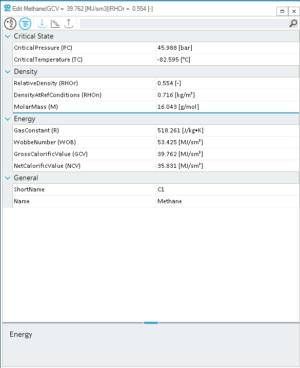
Gas components, as gas qualities, are objects within a network object.
The physical and energy properties (e.g., gross/net calorific value, relative density, molar mass, etc.) of a gas component included in SAInt built-in library cannot be edited. In the case of a custom gas component, specific properties can be described in input.
-
Intro
-
net-input
-
net-read-only
Summaries for the properties and the events of GCMP.
| Extension | Description | UnitType |
|---|---|---|
PC |
Critical pressure |
|
TC |
Critical temperature |
|
GCV |
Gross calorific value |
|
Name |
Object Name. Permitted characters are letters, numbers, and underscore ("_"). The name should start with a letter. The name should be unique for each object type. |
|
NCV |
Net calorific value |
|
RHOr |
Relative density |
|
ShortName |
Short name of fluid component used as an extension to access mixture fraction |
Refer to the following How-Tos for more details on Add a Gas Component, Create and Edit a Gas Quality in the GUI, or How to Import/Export Gas Qualities.