Importing Network & Scenario Data
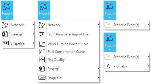
This section describes the different methods to import data from external files in a SAInt project. The user can select different file formats to import data, but Excel templates are preferred over text templates as more user-friendly. A newly added template in shapefile format (*.shp) deals with geographical data for gas networks. The option of importing is available from or from . Figure 1 shows the two buttons and sub-menus used for these two options.
See the section "Template Files" for a description of the available templates to organize external data to create or edit a network, a scenario, a profile, or a gas quality. See the section "Including Network & Scenario Data" for a description of how to include data in SAInt’s native format.
|
An import log file is generated showing any warnings and errors encountered during the import process. The user is advised to check the log for debugging issues. |
1. Importing data into a network
The import features presented in this section only apply to a network and associated objects. These features can be accessed using Import in the data panel under the Network tab.
1.1. Network import file
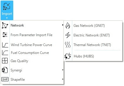
The network import template file is an Excel file that allows defining the properties for each object in a network. Figure 2 shows the sub-menus for the different network types when selecting the option. The template is organized around several sheets for each object type belonging to the network. However, these sheets can be categorized into two groups: the Information sheet and the Unit information sheet define the "Information group", while all remaining object sheets define the "Objects group". Templates are different per network type (GNET, ENET, etc.).
When importing a network, SAInt requires the user to specify a folder where to save the new system. Unlike when creating a new network, the name of the folder selected does not determine the name of the imported network. The name of the imported network is a mandatory parameter in the template, and SAInt uses the user-specified value to name the network.
Furthermore, if the user specifies the same folder for the same import template multiple times, SAInt does not overwrite the imported network but adds "_1" at the end of the network name. In this way each import action results in the creation of a network.
|
Network import files require a minimum of 1 branch connecting 2 nodes. |
1.1.1. Information sheet
The information sheet provides an overview of all the objects' properties, unit type, default values, the applicable scenario type, and the mandatory field for each object. The information sheet is not imported into SAInt. Relevant fields are:
- Extension
-
The extension refers to the properties that can be included for each object.
- Display name
-
The name displayed in the property editor for the objects' properties.
- Description
-
The description of the different object properties included in the network.
- UnitType
-
The type of units associated with the different object properties.
- Default value
-
The default values assigned to the different object properties.
- Applicable for scenario type
-
The list of different scenario types where the object properties are applicable.
- Required
-
Defines the mandatory properties of each object type.
|
1.1.2. Unit information sheet
The UNITINFO sheet provides the user with the available units associated with each unit type. The units in the objects' sheet are specified using square brackets (e.g., cubic meter [m³], US Dollar per Mega Watt hour [$/MWh], EU Euro per Mega Watt hour [€/MWh], etc.). The short form used in SAInt tries to match as much as possible the symbol commonly used in the SI or Imperial system, but differences are possible.
1.1.3. Objects sheet
The objects sheets show all the corresponding properties for each object associated with a network type (e.g., ENET, ESUB, GSUP). Each object type has its own Excel sheet in the template file. The header row of an object sheet describes all the properties, units, and default values of the object, which the user can specify in the network import file. The user is invited to use the header rows as guidelines to define the different properties of any object. The header cells generally use the following convention: "PropertyExtension [unit] = DefaultValue". The user can create a new object by entering the object properties under each corresponding header in a new row. The mandatory properties are highlighted in bold. For optional properties, if no value is entered, they are imported with default values and units.
Coordinates are indicated with "X/Long [km] = 0" and "Y/Lat [km] = 0". Whenever the user is selecting a geographic coordinate reference system, SAInt will interpret the values reported in the two fields as expressed in degrees and decimal fractions of degrees. If the user specifies a projected coordinate reference system, SAInt will use meters as reference unit. It will disregard any unit indicated in square brackets. Only when CRSInfo is equal to NONE, SAInt will interpret coordinates as belonging to a Cartesian plane and with the units indicated in square brackets.
When importing a model using a template, SAint performs a set of checks on the data and the structure described in the file. Errors and warnings are logged, and the user is informed of the import operation’s success, along with the location of the log (if generated). It is highly recommended to review the log to identify and resolve issues with the imported data and to understand any possible changes SAInt may have made during data ingestion.
For example, SAInt does not check the validity of latitude or longitude for any node or vertex. As a result, any value outside the range of minus 180 degrees and plus 180 degrees for the longitude will not be fixed during the import process.
When a value is written in the wrong way (e.g., a string is used in place of a numeric value), SAInt points to the cell/row in the template and informs that a change (generally the use of a default value) occurred.
For containers like "zones" and "subs", when there is a mismatch between the container’s name defined in its sheet and the name used in the node or branch property ZoneName or SubName, the user is notified.
|
The user is recommended to check the validity of the numerical figures and strings in a template. |
Once the user has a good idea of the structure and hierarchy of objects and properties of a network and of a scenario, the use of the templates is straightforward. Some examples of how to fill the network template import file are provided below.
- Hydro generator (Electric network)
-
The HGEN describes a hydro generator connected to a hydro plant in an electric network.
Example: HGEN - (Hydro generator sheet)
Name |
NodeName |
PlantName |
Alias |
C0DEF [€] = 0 |
C1DEF [€/MWh] = 0 |
… |
HGEN_01 |
ENO_00 |
HYDP_UPPER |
||||
HGEN_02 |
ENO_00 |
HYDP_LOWER |
- Electric constraint and variable (Electric network)
-
The ECNSTR and EVAR define a user constraint in an electric network. In the ECNSTR sheet, the user defines the upper and lower limits, while the constraints variables are defined in the EVAR sheet.
Example: ECNSTR - (Electrical constraint sheet)
Name |
Alias |
InService = True |
Info = - |
LowBoundDef [-] = -∞ |
UpBoundDef [-] = ∞ |
Coal_Production |
TRUE |
National_Coal_Limit |
0 |
350 |
Example: EVAR - (Electrical variable sheet)
Name |
CNSTRName |
NetObjID |
ObjVarName = P |
Unit |
Alias |
InService = True |
PLIMIT_COAL_ST00 |
Coal_Production |
FGEN.COAL_ST00 |
P |
[MW] |
Coal_Production |
TRUE |
PLIMIT_COAL_ST01 |
Coal_Production |
FGEN.COAL_ST01 |
P |
[MW] |
Coal_Production |
TRUE |
PLIMIT_COAL_ST02 |
Coal_Production |
FGEN.COAL_ST02 |
P |
[MW] |
Coal_Production |
TRUE |
- Gas quality, gas composition, and gas quality usage (Gas network)
-
The GQUAL, GCMP, and GCUS sheets are used to define the properties, composition, and usage of the different gases available in a gas network. GQUAL and GCMP can both be imported with a gas quality import file.
Example: GQUAL - (Gas quality sheet)
Name |
RHOr [-] |
GCV [MJ/sm3] |
NCV [MJ/sm3] |
PC [bar] |
TC [C] |
DEFAULT |
0.598 |
42.444 |
38.3336 |
46.059 |
-73.246 |
BLEND |
The GCMP section allows the user to create custom gas components. The user can define the component’s name and properties. If no gas properties are defined, the properties will be computed from the specified gas composition.
List of gas components included in SAInt
Gas Components |
Short Name |
Gas Components |
Short Name |
Methane |
C1 |
n Decane |
NC10 |
Ethane |
C2 |
Carbon Monoxide |
CO |
Propane |
C3 |
Carbon Dioxide |
CO2 |
iso Butane |
IC4 |
Hydrogen |
H2 |
n Butane |
NC4 |
Hydrogen Sulfide |
H2S |
iso Pentane |
IC5 |
Water |
H2O |
n Pentane |
NC5 |
Helium |
HE |
n Hexane |
NC6 |
Oxygen |
O2 |
n Heptane |
NC7 |
Nitrogen |
N2 |
n Octane |
NC8 |
Argon |
AR |
n Nonane |
NC9 |
The GCUS defines the molar percentage of each component used in a gas mixture.
Example: GCUS - (GCUS sheet)
[QUAL] |
DEFAULT |
C1 |
93 |
C2 |
5 |
C3 |
2 |
[QUAL] |
BLEND |
C1 |
83.7 |
C2 |
4.5 |
C3 |
1.8 |
H2 |
10 |
- Polyline (all network types)
-
The
POLYsheet modifies the network geometry. It allows the users to add additional intermediate points (i.e., vertexes) to a branch between the X and Y properties of the branch’sFromNodeandToNode. For each polyline, the first row contains the objects identifier "ObjectType.ObjectId" followed by the X and Y coordinates defined from the second row. The end of a polyline is marked by a hashtag (#).
Values for the vertices must comply with the same coordinate reference system used for the nodes.
Example: POLY - (Polyline sheet)
TRF.TRF_1 |
|
-71808.66406 |
-16552.2832 |
# |
|
LI.LI_1 |
|
-76818.09375 |
-11856.60742 |
-76925.55469 |
-11878.73242 |
# |
- Group (all network types)
-
The user can assign different objects to a group using the group sheets (EGRPM for an electric network, GGRPM for a gas network, etc.). The user needs to add the header row (e.g., [GRPM]) to the first cell followed by the group name in the second cell. The objects' IDs belonging to a specific group are defined below the header. For multiple groups, the user needs to add another header row (e.g., [GRPM]) after the last object ID entry of a group and follow the same format described above and shown in the example.
Example: EGRPM - (Group sheet)
[GRPM] |
EGRP.COAL_ST |
FGEN.COAL_ST00 |
|
FGEN.COAL_ST01 |
|
FGEN.COAL_ST02 |
|
[GRPM] |
EGRP.COAL_DD |
FGEN.COAL_DD00 |
- HUB import file
-
The user can create a HUB network by defining the coupled networks in the HUBS import file. The HUB objects are defined in the corresponding sheets (EDGCS, EDGSTR, etc.).
Example: HUBS - (HUB System sheet)
Name |
GNETNAME |
ENETNAME |
Comment |
P2G_00 |
Gas_Grid |
Electric_Grid |
Hydrogen_Electrolyzer_PEM |
P2G_01 |
Gas_Grid |
Electric_Grid |
Hydrogen_Electrolyzer_SOEC |
EDGCS |
Gas_Grid |
Electric_Grid |
Sales_CompressorStation |
EDGSTR |
Gas_Grid |
Electric_Grid |
Hydrogen_StorageFacility |
GFG_00 |
Gas_Grid |
Electric_Grid |
Hydrogen_FuelCell |
GFG_01 |
Gas_Grid |
Electric_Grid |
GasTurbine |
|
The |
1.2. Parameter import file
A parameter import file is a powerful and flexible tool giving the user the option to change objects' properties in bulk. It is a single-sheet import file where the user can change the value and the unit of measure of every parameter in a network. The file format can be either Excel or text file (TAB delimited or comma delimited). The general structure of a row in the file is "Object_Type.Object_Name.Extension → Value → Unit of measure".
The following example showcases the structure of a parameter import file, and it is valid for all network types:
Parameter=ObjectType.ObjectName.ObjectProperty |
Value |
[Unit] |
FGEN.NATURALGAS_CC00.PMAXDEF |
770 |
[MW] |
FUEL.NATURALGAS.FuelPriceDef |
6.25 |
[$/MMBTU] |
GDEM.NG_CC00.QMAXDEF |
600 |
[ksm3/h] |
GFG.CC_FACILITY.HR0 |
7.5886 |
[MJ/kWh] |
GFG.CC_FACILITY.HR1 |
-0.0008 |
[MJ/kWh/MW] |
ENO.NODE1.Alias |
- |
|
ENO.NODE1.Name |
NODE1 |
|
ENO.NODE1.Visible |
TRUE |
|
The parameter import file does not allow to add or remove existing objects. |
1.3. Wind turbine power curve import file
The wind turbine power curve (WTPC) import file allows importing wind turbine power curve(s) into a SAInt project. The WTPC can be assigned to wind generator objects. The import file is a single-sheet file that can be separated into two sections. The definition section sets the properties and units of the wind turbine power curves. The second section defines the relation and values between wind speed and turbine power output. The user has access to an exhaustive database of over 200 WTPCs' import files based on commercial data of over 40 different manufacturers. These import files are located in C:\...\DataImport\WindTurbinePowerCurve. Custom wind turbine power curves can be created.
See the section "Wind Turbine Power Curve Template Files" for more details, or the How-To "Edit a Wind Turbine Power Curve using the Template" for a description on how to use the templates.
|
The WTPC import file can only be imported if an electric network file is open in SAInt. |
Example: WTPC - (Electric network)
%Import template for Power Curve of Wind Turbine,
[UNIT],
VEL,[m/s]
PPOW,[kW]
[DEF],
%WindTurbineCurveName,InterpolationType=0
composite_1,Linear
[DATA] composite_1,
%Wind Speed [m/s],TurbinePowerOutput [kW]
0,0
3.75,0
4,28.5
4.25,46.875
4.5,65.25
4.75,83.625
5,102
5.25,129
5.5,156
5.75,183
6,210
6.25,246.375
6.5,282.75
6.75,319.125
7,355.5
7.25,403.875
7.5,452.25
7.75,500.625
8,549
8.25,607.875
8.5,666.75
8.75,725.625
9,784.5
9.25,851.625
9.5,918.75
9.75,985.875
10,1053
10.25,1110.75
10.5,1168.5
10.75,1226.25
11,1284
11.25,1321.5
11.5,1359
11.75,1396.5
12,1434
12.25,1445.63
12.5,1457.25
12.75,1468.88
13,1480.5
13.25,1483.13
13.5,1485.75
13.75,1488.38
14,1491
14.25,1492.5
14.5,1494
14.75,1495.5
15,1497
15.25,1497.38
15.5,1497.75
15.75,1498.13
16,1498.5
16.25,1498.88
16.5,1499.16
16.75,1499.37
17,1499.53
17.25,1500
17.5,1500
17.75,1500
24.75,1500
25,1500
25.25,0
39.75,0
40,0
1.4. Fuel consumption curve import file
The fuel consumption curve (FCC) import file allows importing fuel consumption curve(s) into a SAInt project. The FCC can be assigned to fuel generator objects. The import file is a single-sheet file that can be separated into a main section and comment lines. The main section sets the name of the fuel curve and defines the relation and values between generator power and fuel consumption. A template for a fuel consumption curve file in text format is located in C:\...\DataImport\FuelConsumptionCurve. The suer can create custom fuel consumption curve files.
See the section "Fuel consumption curve template files" for more details.
|
The FCC import file can only be imported if an electric network file is open in SAInt. |
Example: FCC - (Electric network)
%Import template for Fuel Consumption Curve of Fuel Generator
[DATA] LILLO_DEGUSSA_WKK
P [MW]	FC [FuelUnit/h]
PMIN	28492951415
20.33	90043041695
30.66	186058425308.393
PMAX	316539102255.06
1.5. Gas quality import file
By using a gas quality import file, the user can import several gases and their corresponding qualities into a gas network. The file can be separated into three sections or sheets (GQUAL, GCMP, and GCUS). Each section defines the composition and properties of the different gases available in a network. The user can either define the properties of the gas directly or allow SAInt to calculate the properties based on the components and their mixture.
See the section "Others Template File" for more details on the templates for gas quality, or the How-To "How to Import/Export Gas Qualities" for a description of the import or export process using templates.
|
The gas properties defined in the GQUAL section will override the calculated properties based on the gas composition. |
1.6. Synergi gas
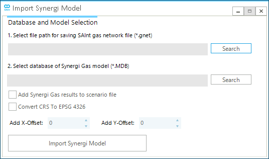
Synergi™ Gas models can be imported directly into SAInt (Figure 1) thanks to a dedicated import procedure. This option is only available for gas networks.
The user must supply a destination path and name for the new network file *.gnet and a source path for the Synergi Gas database file (*.MDB) (Figure 3). The user can optionally select to :
-
import the solution of a solved steady state scenario. The scenario is named STESyn.gsce. Values for the pressure and the flow at each node are mapped to the SAInt node
PREFand the branchQREFfor comparison. The Synergi Gas solution can be used to validate the imported model. -
project the geographic location of the model to SAInt coordinate reference system (i.e., WGS84 or EPSG:4326). The length of branches is not recomputed during the re-projection. By converting, the model is represented on a geographic Map View and a base map is available.
-
offset the position of objects by applying a rigid translation along the x- or y-axis of a user-defined amount. The unit of measure is the one used by the data or origin.
SAInt tries its best to convert the model into a ready-to-use network. All relevant SAInt parameters and variables for all branches and externals are checked, and when Synergi Gas has a valid value, such value is copied. Otherwise, SAInt default values are used. However, because of the substantial differences between the Synergi Gas and SAInt objects, the user is advised to verify the imported model manually.
The units of measurement are maintained during the import of the model.
SAInt generates the following elements after successfully importing a Synergi Gas model:
-
a *.gnet network file with the name specified by the user.
-
the *.lbl, *.plg, and *.vtc files for labels, polygons and vertices. The labels and vertices files can be removed once the model is saved for the first time in SAInt, and the *.GMAP is generated. SAInt does not recognize annotation and polygons in Synergi Gas, so the user must rebuild such objects in its project.
-
a STESyn.gsce scenario file where the events for a scenario are defined. If the corresponding table in Synergy Gas is fully populated, SAInt will copy the list of events and constraints. Otherwise, a short list describing general constraints for facilities and network properties is created. For example, if quality tracking must be activated or not (the default is to turn it off) or the control mode for certain facilities (e.g., control valves or compressor stations set to
PSET). The complete list depends on the complexity of the model and on the level of details the user implemented. -
a text file called "STEsyn.txt" where - if any - the events for a scenario are defined. The content of this file determines the content of STESyn.gsce. The table has the following columns: "Parameters", "Value"(i.e., the numeric figure for the parameter), "Unit" (i.e., the unit of measure of the numerical value), "Condition" (i.e., the condition for the event), "EvaluationType" (i.e., the evaluation type for the condition), "Active" (i.e., is the event is active or not), and "Info" (i.e., a text string providing a description).
-
a text file called "SceEventImportResults.txt" where the results of a simulation - if any - are provided in a tabular format with columns: "Parameters", "Value" (i.e., the numeric figure for the parameter), "Unit" (i.e., the unit of measure of the numerical value), and "ProfileName" for a profile to be used for the parameter in dynamic simulations.
-
a text file called "SceEventImportWithProfile.txt" containing a list of events for the externals and branches from the Synergy Gas model. The same columns available in "SceEventImportResults.txt" are present. This file could be used for generating dynamic scenarios in SAInt.
Furthermore, SAInt will perform the following:
-
generate an external for each flow category used in Synergi Gas at each node.
-
import the profiles used in Synergi Gas.
-
convert a Synergi Gas storage from a branch object to an external.
-
use a GSUP object for LNG facilities as such entity are not modelled as specific objects in Synergi Gas.
It is possible to specify the level of logging the SAInt performs when importing and converting a Synergi model. The user can set the property SynergiImportLogFileLogLevel from "verbose"up to "fatal". See "Miscellaneous" for more details.
For an example of the import procedure refer to the How-To guide "Import a Synergi Gas mdb File".
|
SAInt imports Synergi Gas models in Microsoft Access® Furthermore, SAInt has no "export" capability toward Synergi Gas. |
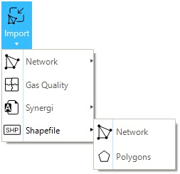
1.7. Shapefile network
SAInt allows importing of network data using the shapefile data format (Figure 4). The user is required to select the network type (i.e., an electricity or gas network), and to map the attributes from the original shapefile to the corresponding properties of SAInt objects. The mapping can be saved and reused later. 3D features are not yet supported. The elevation is imported as an attribute by means of parameter import files, and not as part of the geometry. After the first shapefile is correctly imported, the user can select other files and repeat the procedure.
SAInt assumes the network data to be organized around a specific "data model". Fluid pipelines or electric lines must be saved in a shapefile using polylines. All other facilities must be described by points in a separate file, with a shapefile for each type of facility. All shapefiles must be in the same projected coordinate system, and topological or geometric errors must be addressed before importing the data.
The first element to be imported must be either a pipeline or an electric line. Any other facility must be after creating a basic network out of those two types of branches. If a facility is not located at the start or end of a branch, SAInt will split the branch at the nearest vertex.
When importing data from a shapefile dataset, SAInt interprets the coordinates as meters and does not perform any conversion. It is recommended to avoid the use of geographic coordinates (i.e., latitude and longitude), but to prefer projected systems. SAInt does not identify or recognize the coordinate system during import.
SAInt does performs some basic checks during the import of data, like for example when the from and to node are the same for a branch, and drops entities not matching its basic criteria. The user is advised to always check the import log, even when the operation is successful.
See the How-To "Import Network Data in Shapefile Format" for a detailed description of the import wizard for the case of a gas network. Or use "the templates in shapefile format", provided in .\DataImport\ShapeFile\Gas, to organize and transfer data from an existing Geographic Information System (GIS) database.
1.8. Shapefile polygon
The user can add polygon objects in the background of the map window. Polygon objects are imported using data in shapefile format. The graphic properties of the polygons can be personalized.
Polygons are only supported in Cartesian Map Views.
See the How-To "Import Polygons From a Shapefile" for a detailed description of the import function.
|
The files |
|
2. Importing data into a scenario
The import features presented in this section only apply at the scenario level (Figure 1 right). These features can be accessed using Import in the data panel under the Scenario tab.
2.1. Scenario event import file
The scenario event import file is an Excel file that allows defining the events for each object in the network. The "template" is separated into several sheets for each object type belonging to the network. However, these sheets can be categorized into three main groups: "information sheet", "unit information sheet", and "event sheet" (ESCE, GSCE, etc.). Templates are different per network type (ENET, GNET, etc.).
2.1.1. Information sheet
The information sheet provides an overview of all the events that can be applied to the objects, along with the unit type, default values, for which scenario they are applicable and mandatory fields for each object. The information sheet is not imported.
The details provided in the information sheet are:
- Parameter
-
The parameter refers to the events' extension that can be assigned to each object.
- Description
-
The description of the properties of the different events included in the network.
- Applicable for scenario type
-
The list of different scenario types where the object events are applicable.
- UnitType
-
The type of units associated with the different events.
2.1.2. Unit information sheet
The UNITINFO sheet provides the user with the available units associated with each unit type. The units in the scenario events sheet (ESCE, GSCE, etc.) are specified using square brackets (e.g., cubic meter [m³], US Dollar per Mega Watt hour [$/MWh], EU Euro per Mega Watt hour [€/MWh], etc.).
2.1.3. Event sheet
The scenario event sheet shows all the events and their properties for a certain scenario. The structure of the event sheet file is very flexible and described in the section "Scenario events template". Though multiple file formats are available, the Excel file format is the preferred one.
|
|
If the event start time is outside the simulation window, the event is not imported, and the user is informed in the import log file. |
2.2. Profiles import file
The profile import file allows users to import profiles. The import file can be separated into the profile description and data sections. The profile description section defines the name and properties of the profile. The data section defines the data values used to create the profile. A profile import file can be formatted as a single-sheet file either in Excel or in text format. See the section "Profile Template" for a detailed description of the template for profiles and for examples.
|
|
If a profile is declared in the "profile description" section but no time series is provided in "profile data" section, the profile will not be imported. If a profile is defined as a time series in the "profile data" section but it is not declared in the "profile description" section, the profile will not be imported. |