Exporting Network & Scenario Data
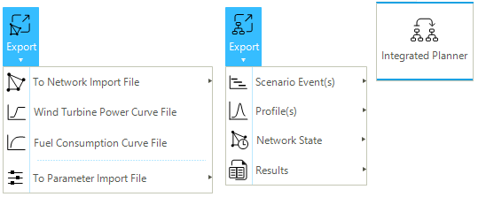
This section describes the different methods to export data from a SAInt project. The user can select different file formats to export data to, but native SAInt formats or the Excel file format are preferred over text or comma-separated versions as more user-friendly. The option of exporting is available from or from . Figure 1 shows the two buttons and sub-menus used for these two options.
|
|
Including SAInt native files is faster than importing other formats. |
1. Exporting data from a SAInt network file
The export features presented in this section only apply at the network level. The user can use these features to export data from the current network file to create SAInt native or import files (Excel, text, etc.). A network must be active to access the export options.
1.1. Export to network import file
The first option accessible from is To Network Import File (Figure 1 left). A network import file, based on reference multi-sheet template, can be generated by exporting network data from the active network model. The sub-menu lists the type of networks that can be exported based on the networks available in the active project. Possible file formats are Excel, comma-separated text files, or text files.
If the active network is displayed on a Cartesian Map View, the export procedure writes the objects’coordinates as they are saved in the network file. If the network is showed on a geographic Map View, SAInt allows the user to convert the coordinates by specifying a target CRS for the newly generated import file.
Sections "Coordinate Reference Systems" and "Map view" provide more details on how SAInt handles coordinates and coordinate reference systems.
|
If an object type is not present in the network, no sheet will be generated for that object type. |
1.2. Export to wind turbine power curve file
The second option accessible from is To Wind Turbine Power Curve File (Figure 1 left). A "wind turbine power curve file" can be created by exporting the wind turbine power curve data from the network model opened in SAInt. If several wind turbine power curves have been imported, they can be aggregated by exporting them to a wind turbine power curve file. This option is only available when an electric network is part of the active project. The only possible file format is the SAInt native file format *.wtpc.
|
This file can be created to represent a set of predefined wind turbine power curves. |
1.3. Export to fuel consumption curve file
The third option accessible from is Fuel Consumption Curve File (Figure 1 left). A consumption curve file is generated, using a "reference template", by exporting the existing curve data from the network model opened in SAInt. If several fuel consumption curves have been imported, they can be aggregated by exporting them to an external file. This option is only available when an electric network is part of the active project. The only possible file format is the SAInt native file format *.fcc.
1.4. Export to gas quality import file
The fourth option accessible from is To Gas Quality Import File (Figure 1 left). A gas quality import file can be created, using a "reference template", by exporting the gas quality data from the network model opened in SAInt. The option is only available if a gas network is part of the active project. Possible file formats are Excel, comma-separated text files, or text files.
1.5. Export to parameter import file
The last option accessible from is To Parameter Import File (Figure 1 left). A parameter import file can be created by exporting, using a reference template, network data for a network of the active project in SAInt. If multiple networks are available, the user must select one. Possible file formats are Excel, comma-separated text files, or text files.
|
If the user needs to edit/correct multiple object parameters of a network, use the export to parameter import file to obtain a complete list of all the object parameters included in the SAInt network model. The user can then edit this file and import it back to SAInt. |
1.6. Export to a new polygons file
It is possible to "export" SAInt polygons to a new copy of a SAInt native polygons file. A polygons file does not hold network-specific information, so the same polygons set can be exchanged among different projects. The only possible file format is the SAInt native file format *.plg.
To export the polygons, select the entry "Polygons" in the Model Explorer and right-click. From the context menu, choose Export Polygon(s).
2. Exporting data from a SAInt scenario file
The export features presented in this section only apply at the scenario level. The user can use these features to export data from the active scenario to create SAInt native or import files (Excel, text, etc.). A scenario must be active to access the export options.
2.1. Export to scenario events import file
The first option accessible from is To Scenario Event Import File (Figure 1 right). A scenario event import file can be created by exporting, using a "reference template", scenario event data from the scenario file opened in SAInt. An active scenario is required, and the event import file is specific to the network associated with the scenario. Possible file formats are Excel, comma-separated text files, or text files.
|
The scenario import file can be useful when designing a similar scenario. For example, if a model contains several scenarios with common events, this feature can be used to import the common ones. |
2.2. Export to profile file
The second option accessible from is To Profile File (Figure 1 right). A profile file can be created by exporting, using a "reference template", the profile data from a scenario file active in a project of SAInt. The user can extract all or a set of the profiles included in the active scenario.
Supported file formats are: SAInt native *.prf, Microsoft Excel®, comma-separated values (CSV) and ASCII text.
|
Profiles can be transferred from one scenario to another regardless of the scenario type. |
2.3. Export to network state file
The third option accessible from is To Network State File (Figure 1 right). A network state file allows exporting of the results of a simulation of a scenario for all the objects of the active network at a specific timestep. The displayed time in the map view represents the timestep of the simulation for the active scenario. The only possible file format is the SAInt native file format *.*con.
|
A state file can be used to set initial conditions for another scenario file of the same network file. |
2.4. Export to results file
The last option accessible from is To Result File (Figure 1 right). A results file can be created to extract inputs and outputs of the SAInt model for a specified time window. The export procedure is a two steps procedure, requiring the user to specify first a "results description file", and after to provide the name and location of the results output file. Possible file formats for the description and output files are Excel, comma-separated text files, or text files.
- Results Description file
-
A results description file allows the user to specify a list of results properties to be extracted and saved in a result file. The user must define the list of the result properties using object identifier syntax "ObjectType.ObjectName.Extension.[Unit]". The results will be extracted using default units if no unit of measure is specified. Default units are the ones specified by the user in the tab "Units" of the general settings when in the GUI. When using the API, SAInts uses as default units based on the International System. When using the API, the user can either specify the units by loading a units file with the method
.LoadUnitsor by explicitly indicating the units in the results description file.
Example of a results description file using a mix of user-specified units and default units.
PV.SOLAR.P.[kW]
WIND.ONSHORE_WIND.P.[MW]
HGEN.HYDRO.P
ESTR.BATTERY_STORAGE.P
- Results Output file
-
The results output file contains all the exported data in a tabular form. The first two columns, "Time [sec]" and "DateTime [dd/MM/yyyy HH:mm]" show the scenario time in seconds, and in a date format, the successive columns contain the result data requested in the description file.
Example of the output of a results description file
Time [sec] |
DateTime [dd/MM/yyyy HH:mm] |
PV.SOLAR.P [kW] |
WIND.ONSHORE_WIND.P [MW] |
HGEN.HYDRO.P [MW] |
ESTR.BATTERY_STORAGE.P [MW] |
0 |
1/1/2021 |
0 |
0 |
0 |
0 |
3600 |
1/1/2021 1:00 |
0 |
39.68 |
157.8026572 |
-131 |
7200 |
1/1/2021 2:00 |
0 |
36.145 |
157.8026572 |
-131 |
10800 |
1/1/2021 3:00 |
0 |
32.7 |
157.8026572 |
-131 |
14400 |
1/1/2021 4:00 |
0 |
28.2775 |
157.8026572 |
-131 |
18000 |
1/1/2021 5:00 |
0 |
25.3625 |
157.8026572 |
-131 |
21600 |
1/1/2021 6:00 |
0 |
21.8125 |
157.8026572 |
-131 |
25200 |
1/1/2021 7:00 |
0 |
20.395 |
157.8026572 |
-131 |
28800 |
1/1/2021 8:00 |
10 |
20.0275 |
157.8026572 |
-131 |
32400 |
1/1/2021 9:00 |
60 |
21.3525 |
157.8026572 |
-131 |
36000 |
1/1/2021 10:00 |
340 |
21.8425 |
157.8026572 |
0 |
39600 |
1/1/2021 11:00 |
820 |
19.7425 |
263.1640013 |
-131 |
43200 |
1/1/2021 12:00 |
1200 |
16.895 |
263.1640013 |
0 |
46800 |
1/1/2021 13:00 |
1350 |
13.79 |
263.2166718 |
0 |
50400 |
1/1/2021 14:00 |
1250 |
12.2175 |
263.425224 |
68.5184372 |
54000 |
1/1/2021 15:00 |
880 |
12.9525 |
262.4107091 |
166 |
57600 |
1/1/2021 16:00 |
360 |
16.26 |
261.1318323 |
0 |
61200 |
1/1/2021 17:00 |
60 |
22.245 |
259.9123515 |
0 |
64800 |
1/1/2021 18:00 |
0 |
30.3775 |
260.7247587 |
0 |
68400 |
1/1/2021 19:00 |
0 |
36.9825 |
262.2949426 |
166 |
72000 |
1/1/2021 20:00 |
0 |
40.6475 |
263.5916479 |
166 |
75600 |
1/1/2021 21:00 |
0 |
43.035 |
266.2708229 |
166 |
79200 |
1/1/2021 22:00 |
0 |
45.7 |
266.9432298 |
166 |
82800 |
1/1/2021 23:00 |
0 |
48.54 |
268.3066597 |
166 |
86400 |
2/1/2021 |
0 |
47.5675 |
196.7854678 |
166 |
3. Exporting data to a new SAInt scenario file: the Integrated Planner tool
The Integrated Planner button from the "Scenario" tab allows access to the "Integrated Planner" tool to generate transfer files for events and profiles (Figure 1, right). An electric network with a solved steady state ACPF or UACPF, a solved quasi-dynamic ACPF or a solved DCUCOPF scenario is required to have the "Integrated Planner" tool active. SAInt allows users to transfer the results of a simulation or optimization to a new scenario as events and profiles for new analyses. This special "export" capability facilitates different types of analyses and workflows, like, for example carrying out a more detail assessment of a specific time period withing a parent scenario (i.e., a peak period withing a longer time windows for an initial scenario), or like assess physical constraint using a quasi-dynamic ACPF approach out of the results of an optimization analysis with a DCUCOPF scenario for a specific week out of a one-year hourly optimization problem. The tool enables the user to switch the type of analysis between steady state and quasi-dynamic, or between (U)AC(O)PF / DCPF and DCUCOPF, and in doing so, combine physical and economic models.
Not all possible combinations are allowed in the "Integrated Planner". For example, from a steady state ACPF, it is possible to export results or events to a steady state DCPF, ACPF, ACOPF or UACPF scenario. From a steady state DCPF, it is possible to export results or events to a steady state DCPF, ACPF, ACOPF or UACPF scenario. From a steady state UACPF, it is possible only to export results or events to another steady state UACPF. From a quasi-dynamic ACPF scenario, it is possible to transfer events or results to any of the four types of steady state scenarios (i.e., (U)AC(O)PF and DCPF), or to a quasi-dynamic ACPF, ACOPF, UACPF or DCPF scenario. From a quasi-dynamic UACPF, it is possible to transfer to a steady state UACPF or a new quasi-dynamic UACPF. Or, from a DCUCOPF optimization, it is possible to transfer events or results to a new DCUCOPF optimization or to any of the steady state or quasi-dynamic ACPF, ACOPF or UACPF scenarios. SAInt provides access only to acceptable combinations of scenario types.
The "Integrated Planner" tool allows to move from one solved scenario to a newly generated user-specified scenario two different "configuration types": the "pass through configuration" and the "transfer configuration". A "Pass-through" configuration transfers all events, "on/off" status, "minimum and maximum" boundaries, or a user-defined custom subset of events from the solved scenario over to the new scenario, which may have the same start and end time, or a different time window (within the time window of the parent scenario). A "transfer" configuration focuses on moving from a DCUCOPF parent scenario the object’s commitment events (ON or OFF state), and/or the dispatch and demand events (P variable of the objects).
To complete a "Integrated Planner" operation, the active scenario must be solved. In case of an unsolved active scenario, SAInt will inform the user that the transfer operation cannot be performed and request that the scenario be solved.
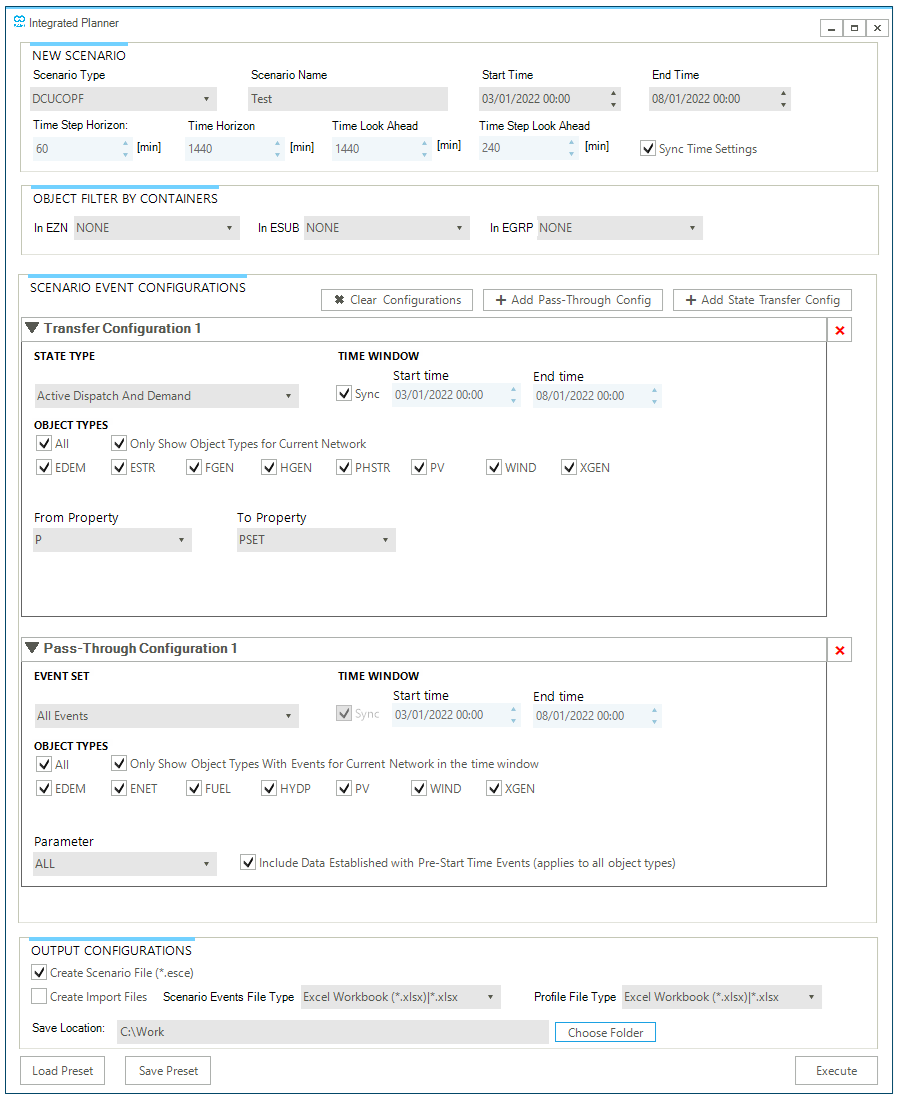
The "Integrated Planner" form (see an example in Figure 2) has four main sections: (1) the "New Scenario" section, (2) the "Object filter by Containers" section, (3) the "Scenario Event Configurations" section, and (4) the "Output Configurations" section.
In the New Scenario section, the user specifies (1) the type of new scenario to be generated from the results of the active scenario by means of a drop-down menu, (2) the name of the new scenario, and (3) the "Start Time" and the "End Time" for the new scenario. Depending on the selected scenario type, SAInt may show the "Time Step Horizon" or "Time Step" and may also report the "Time Horizon", the "Time Look Ahead", and the "Time Step Look Ahead". By default all values are copied from the active solved scenario. But it is possible to uncheck the option "Sync Time Settings" to allow modifying these time settings, with the only exception of the "Time Step Horizon" which is fixed. In this way, it is possible to define a shorter time window with a coarser time granularity.
In the Object filter by Containers section, it is possible to select an existing container to restrict any transfer operation to only the objects of that subset of the network. The default is not to filter the active model for any container. It is possible to combine objects from different containers, for example, by selecting an ESUB and a EZN. It is important to note that the set of available objects or events provided in any "Pass-Through Configuration" or "Transfer Configuration" is filtered at execution time and not when selecting a container. An EZN will filter the nodes that are included, branches with a FromNode or ToNode included, and externals linked to included nodes. A ESUB will filter any node linked to a branch included in the sub, any branch included, and any external in an included node. A EGRP will include nodes, branches or externals which are part of the group.
In the Output Configurations section, the user specifies the save location for the new scenario, along with the option of which files to generate. It is possible to create a SAInt native "*.esce" scenario file along events and profiles files in non-native SAInt formats, like Excel, CSV or TXT. The SAInt native format is particularly useful as it allows the immediate execution of the new scenario. Only one file per type is created even if multiple configurations are specified.
The section Scenario Event Configurations is the most complex and flexible, covering multiple cases. Here, the user can specify what to transfer from the active solved scenario to the new scenario. Multiple configurations can be specified by either selecting a "pass-through configuration" or a "transfer configuration". Once the type of configuration is chosen, a sub-form allows the user to specify the objects, the time settings, and the properties to transfer.
For example, if we need to transfer the PSET property of EDEM objects and the PMAX property of WIND objects, it is necessary to use two pass-through configurations, one for each coupled parameter - object.
If a "Transfer Configuration" is selected, the user can define:
-
the State Type: from a drop-down list, it is possible to choose between "Active Dispatch and Demand", "Unit Commitment", or "Custom" (i.e., user-defined subset of data covering multiple objects and results).
-
the Time Window: it is possible to specify a "Start Time" and "End Time" value for each transfer configuration. If the checkbox "Sync" (i.e., synchronize) is selected, the values are taken from those specified in the "New Scenario" section. If it is not selected, the user can edit those time properties with the values within the time frame defined for the new scenario (i.e., for example the start time cannot be earlier the scenario start time).
-
Object types: a list with checkboxes of objects to be transferred and a mapping between properties from the solved scenario to the state transfer scenario. The user can also specify for each parameter a multiplier when there is a need to scale the exported results. The multiplier will be used as the value of the transferred event, and the event linked to a newly generated profile representing the figures of the property from the parent scenario. Furthermore, a checkbox labelled "Only Show Object Types for Current Network" allows the see only the objects which are present in the active network versus the full list of object for a network of that type. And another checkbox labelled "All" allows to quickly select/unselect all listed checkboxes for objects.
If a "Pass-Through Configuration" is selected, the user can define:
-
the Event Set: from a drop-down list, it is possible to choose between "All Events", "On / Off", "Max / Min", and "Custom" (i.e., manually specify the subset of events of interest).
-
the Time Window: it is possible to specify a "Start Time" and "End Time" value for each transfer configuration. If the checkbox "Sync" (i.e., synchronize) is ticked, the values are taken from the ones specified in the "New Scenario" section. If it is unchecked, the user can edit those time properties with the values within the time frame defined for the new scenario (i.e., for example the start time cannot be earlier the scenario start time).
-
Object types: a list with checkboxes of objects and their properties to be transferred from the solved scenario to the new scenario. It is possible to choose to see only objects available in the network and with events in the configuration time window with the checkbox "Only Show Types With Events for Current Network in the time window" or all objects. And it is possible to quickly select/unselect all listed checkboxes for objects using the checkbox "All".
Finally, the "Parameter" drop-down menu lists the available parameters based on the objects selected and the events available for those objects. If different types of objects are selected, only the parameters in common are reported. Once a parameter is selected, it is possible to transfer only the values for a valid event within the specified time window, or to include also data representing events established before the "Start Time" for the configuration. The default is to add pre-start time events to the transfer dataset (i.e., the option "Include Data Established with Pre-Start Time Events (applies to all object types)" is checked by default). The pre-start time events may be events not linked to the objects selected in the user-specified time window (e.g., all events related to ENET) but required in the new scenario as well. To ensure their transfer, the option is selected by default.
When both "All" and "Only Show Types With Events for Current Network in the time window" are unchecked, the list of parameters reported is the full list of options for the selected object. It is possible to select a parameter for which no event has been specified. In this case, the transfer will be empty.
All editable fields are in gray, while not editable fields are in light blue. The "From Property" and "To Property" fields are not editable, but it is possible to change their content to perform a filter operation to quickly find the property of interest in a long drop-down menu.
Once a configuration or a set of configurations is specified, it is possible to save the settings to a "transfer preset" file, which can be later loaded, so that the user does not have to specify again manually all the details of each configuration. Use the button Load Preset and Save Preset to load and save. "Preset configuration" files have the extension "*.tran" and are created in the same folder specified in the "Save Location" field.
For step-by-step examples of how to use the "Integrated Planner" tool see the following How-Tos:
-
"State transfer from a DCUCOPF to a QuasiDynamicACPF scenario" showcasing how to move from a production cost model to an assessment of the validity of the the solution using using an ACPF approach;
-
"Send unit commitment from one DCUCOPF scenario to another" showcasing how to refine your production cost model by fixing the status of generators from another DCUCOPF scenario;
-
"Comparing Node Voltages Between Two Scenarios" showcasing how to use the output of an ACPF scenario as a reference for another scenario on the same system.
|
If a generator is always on during DCUCOPF, no |