Including Network & Scenario Data
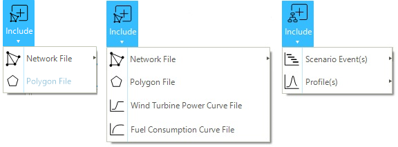
This section provides an overview of the different methods to include, in the active project, data from SAInt native files. SAInt native files are generated during a working session or after using export methods (described in "Exporting Network & Scenario Data"). Different SAInt data files can be included either at the network or scenario levels, but the associated options are - generally - available when a network or a scenario object is active. The option of including is available from or from . Figure 1 shows the two buttons and menus used for including data.
|
SAInt native files are formatted using the Extensible Markup Language (XML). The user is discouraged from editing or manipulating these files manually. |
1. Including data to a SAInt network file
The options presented in this section are available either from an empty project or when a network model is active. The user can choose these options to add data to the network using existing SAInt native files. These options can be accessed using Include in the data panel under the Network tab and cover vertices, labels, polygons, and wind turbine power curve data (Figure 1, left and center).
1.1. Include a network file
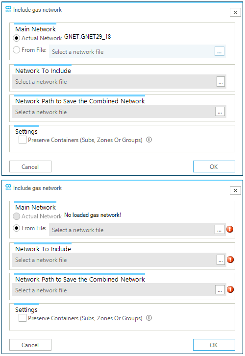
SAInt allows the inclusion of already developed single-energy carrier networks into an existing network of the same type. Hubs cannot be included. Figure 2 shows the interface for including an external network into a network available in an active session of SAInt (top) or for including an external network into another network when an empty project is active in a SAInt session (bottom). The option is available via the menu .
When including an external network to a network available in the active session (Figure 2, top), the user must specify the name of the "Network To Include" and the "Network Path to Save the Combined Network". The "Main Network" field reports the name of the active network. Finally, there is an option to preserve subs, zones, or groups from the incoming network. SAInt may change the names of duplicate objects by adding "_1" (or "_2" and so on).
When including an external network to a network not available in the active session (Figure 2, bottom), the user must, first, specify the file of the "Main Network" in the "From file" field, and after the "Network To Include" and the "Network Path to Save the Combined Network". Again, the "Preserve Containers" is an option.
It is important to note that the location of the network to be included and the joined network must be different (see exclamation mark symbol in Figure 2, bottom). SAInt performs a check and if paths and names are the same, it prevents the operation.
After successfully including the new network, the user must check the new topology of the "joined" system. Data are included as they are, and duplicates are not removed. For example, network two is a planned expansion of network one, and the two are joined at "Node_42". when network two is included in network one, there will be two overlapping nodes named "Node_42" from network 1 and "Node_42_1" from network 2. The two networks are also physically separated. The user must manually merge them at the location of the common node. Select first "Node_42" and after "Node_42_2", and from the context menu, select the option to join nodes. The two are merged, and the second is deleted.
|
The externals associated with a deleted node are removed. When joining two nodes after including a network, the user must take care of adding the removed externals. |
|
SAInt allows to disconnect a branch from a network at a given node. The user must select the branch and the node where to disconnect — either the one as |
1.2. Include polygon data
The polygon file contains the coordinates and properties of the polygons used in your active project. Polygons are mainly used for visualization purposes, and to describe sub-systems or groups. The file extension for the polygon file is *.plg.
By including an existing polygon file, the user can modify the background shown in the map view (e.g., the boundary of a country’s border or the area indicating a particular sub-system of interest).
The option requires the user to specify the polygon file to include. To solve a scenario in SAInt the polygon file is not mandatory. The option is available via the menu .
In release 3.5 of SAInt polygons are supported only in a Cartesian map view.
|
By default polygons are not loaded in a project. To activate the option, select the project entry in the Model Explorer, and open the property editor. Check the option |
1.3. Include wind turbine power curve data
SAInt provides the user with a rich database of wind turbine power curve data already formatted and ready to use. The data are organized in directories and available from the DataImport folder in text format. The text format lets the user inspect quickly the data, and it is compliant with the "import option" of SAInt.
The native SAInt format file extension for the wind turbine power curves is *.wtpc.
The files contain the relation between wind speed and power for different types of wind turbines and manufacturers. This is the quickest way of exchanging data on wind turbines between two projects.
1.4. Include fuel consumption curve data
SAInt provides the user with the functionality of including fuel consumption curves exported from existing projects. The native SAInt format file extension for the wind turbine power curves is *.fcc.
The files contain the relation between the fuel generator power and the fuel consumption. This is the quickest way of exchanging data on fuel generators between two projects.
2. Including data to a SAInt scenario file
The options presented in this section are only available when a scenario is active. The user can choose these options to add data to an active scenario using existing SAInt native files. These options can be accessed using Include in the data panel under the Scenario tab and cover scenario events and profiles (Figure 1 right).
2.1. Include scenario event(s) data
The scenario event(s) file contains all the scenario events of another scenario. The user can transfer the scenario events from an existing scenario to the active SAInt project environment by including the scenario file. The SAInt native extension for a scenario file is *.esce for electric scenarios or *.gsce for gas scenarios.
Scenario event(s) files are successfully included only if applied to the same network model. It is important to remember that an event is assigned exclusively to a specific object. That particular object has a unique identification code, used by SAInt to build relationships between the object and a list of possible events. If the identification code is missing, all events pointing to the code will be lost and not included.
When including events, SAInt may require the user to specify a valid time window based on the time window of the active scenario. Events outside the active time window are clipped.
When including a scenario with events linked to profiles, the profiles are transferred as well and they may be clipped to match the time window of the active scenario.
|
This method helps copy events from one scenario to another. |
|
SAInt does not allows for duplicated events in steady state scenarios. |
2.2. Include profile(s) data
The profile(s) file contains profiles to be used in the active scenario. This option is only available with dynamic scenarios. The user can transfer the profiles used in a previously analyzed dynamic scenario, to the active scenario. The SAInt native extension for a profile file is *.prf.
Differently from the scenario events file, a profile file can be successfully included regardless of the properties of the target dynamic scenario. If the receiving scenario has already profiles with the same name, the names of the profiles included are modified by appending _N, where N is a natural number.
|
Profiles are attributes of a scenario and are saved in the *.esce or *.gsce file. |