Energy System Model Structure
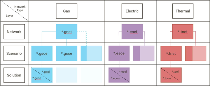
An energy system model in SAInt consists of three layers: network, scenario, and solution (Figure 1). SAInt allows the user to create different layers of energy networks, and each network can be linked to an infinite number of scenarios. The solution file is created upon the successful execution of a scenario. Users can organize several network files into a single project. The collection of scenario and solution files associated with a particular network represents a session. When using the SAInt graphical user interface, a user can access one session at a time. The user can visualize the network and view tables and charts related to the scenarios and any solutions present in a given session using the map window.
1. Networks
A network is a directed graph consisting of a set of elementary object types called nodes, branches, and externals that are connected to one another. A network may contain other types of auxiliary objects that are subsets of or represent relations between the elementary object types. A network contains a description of all geometric, topological, relational, and static properties of all the objects which typically do not change during the execution of a scenario (e.g., diameter or length of a pipeline). The information of a network is saved to a file with the file extension *.*net (e.g., *.enet for electric network, *.gnet for gas network, etc.). A network can represent a distribution or transmission network, a nodal or zonal market, an islanded system, a microgrid, etc.
2. Objects
An object is a unique entity in a network model. Objects span from simple building blocks up to full network instances. They can be subdivided into different classes, each representing a type, such as nodes, branches, externals, networks, subs, zones, and groups. The most fundamental object types are nodes, branches, and externals, as they are the fundamental blocks for building a network model. SAInt has a certain number of classes of "base objects", which describe real-world physical elements and facilities of a gas, electric, or coupled network in mathematical terms. A base object is characterized by a set of properties and by the way it relates to other objects of a different type. SAInt makes a distinction between "child" and "parent" objects. A base object that depends on its existence from another type of base object is said to be its child. A base object encompassing or containing other types of base objects is said to be a parent. In this way, it is possible to organize all base objects in a defined hierarchy of parent and child objects. A full list of base objects is provided in the tables of section "SAInt Objects Overview".
3. Scenarios
A scenario is a case study performed on a network. It is characterized by a scenario type (e.g., SteadyGas, SteadyACPF, QuasiDynamicACOPF, DCUCOPF, etc.), a time window (start time, end time), and the definition of settings, controls, and constraints and how they change over time (described by events and profiles). The mathematical model describing a scenario (type) can be either a simulation or an optimization. The information contained in a scenario is saved to a file with the file extension *.*sce (e.g., *.esce for electric network scenario, *.gsce for gas network scenario, etc.). SAInt’s unique feature allows simulation and optimization scenarios on the same network (e.g., ACPF, UACPF, and DCUCOPF). To learn more about SAInt scenarios see section "Scenarios in SAInt".
4. Solutions
A solution describes the computed results for the variables of a network model for every calculated time point of a scenario. The solution of a scenario is saved to a solution file with the file extension *.*sol (e.g., *.esol for electric network solution, *.gsol for gas network solution, etc.). A condition/state file represents one time step of the solution file and it is saved to a condition file with the extension *.*con. Results are divided into base results and derived results. Base results are saved in the solution file while the derived are calculated from the base results when requested by the user. All base results are saved to the solution file. This means the user can always access whatever information is desired from any solution. For example, a base result for an electric line in a AC-scenario is P - the active power flow along the line. A derived result for an electric line in a AC-scenario is LLP - the line loading given as ratio between active power (P) and maximum active power.